
18
35
HOT IN
NEUTRAL IN
GROUND IN
GROUND OUT
HOT OUT
“FOR USE WITH COPPER WIRE ONLY”
NEUTRAL OUT
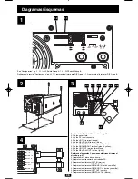
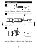
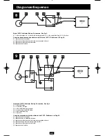
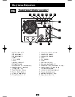
Diagramas/Esquemas
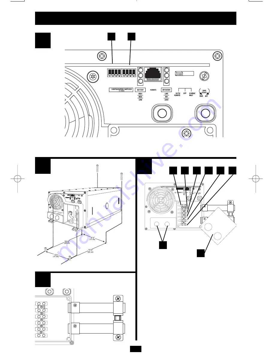
See “Configuration”, pg. 5. 1.1 is DIP Switch Group A. 1.2 is DIP Switch Group B.
Refiérase a la sección “Configuración”, pg. 22. 1.1 representa el Interruptor DIP, Grupo A. 1.2 representa el Interruptor DIP, Grupo B.
See Hardwire Electrical Connections, pg. 10.
3.1 is the cover plate;
3.2 is the DC input connector;
3.3 is the HOT IN terminal (brown);
3.4 is the NEUTRAL IN terminal (blue);
3.5 is the GROUND IN terminal (green & yellow);
3.5 is the GROUND OUT terminal (green & yellow);
3.6 is the HOT OUT terminal (black); and
3.7 is the NEUTRAL OUT terminal (white).
Refiérase a la sección Conexiones eléctricas directas al
circuito, pg. 27.
3.1 representa la placa de cobertura;
3.2 representa el conector de entrada de CC;
3.3 representa el terminal HOT IN (marrón);
3.4 representa el terminal NEUTRAL IN (azul);
3.5 representa el terminal GROUND IN (verde y amarillo);
3.5 representa el terminal GROUND OUT (verde y amarillo);
3.6 representa el terminal HOT OUT (negro); y
3.7 representa el terminal NEUTRAL OUT (blanco).
1
1.2
2
3
1.1
3.3
3.4
3.5
3.6
3.7
3.2
3.1
HOT IN
NEUTRAL IN
GROUND IN
GROUND OUT
HOT OUT
“FOR USE WITH COPPER WIRE ONLY”
NEUTRAL OUT
4
3.8
200201192 UL-Listed APS Manual- trans..qxd 5/17/02 12:40 PM Page 18
Содержание APS 1024 INT
Страница 40: ...93 2035 200201192 40 ...