4096-629
PRODELIN CORPORATION
.89/.98M Ku-BAND Rx/Tx SERIES 1892/1982
15
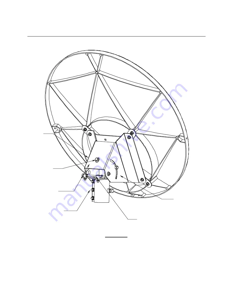
‘A side’
Scale not
used on this
system
Tighten
canister after
rough
adjustment
Reflector Support
‘B side’
scale
for elevation
adjustment
Fine azimuth
adjustment
Elevation
Adjustment Bolt
FIGURE 2.


