16
D01-060en202008 Manual nanoFlu
Use
Calibration
Malfunction &
Maintenance
Introduction
General
Information
FA
Q
Technical Data
W
arranty
Customer
Service
Contact
Keyword
Index
Accessories
Commis-
sioning
Commissioning
//
nanoFlu
2
1
3
G2 interface box
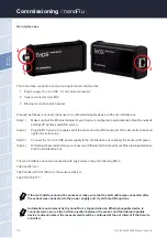
There are three connectors on the housing of the G2 interface box:
1.
Power supply 12 or 24 VDC; 2.1 mm barrel connector
2. Sensor connector 8-pin M12
3.
Ethernet connection RJ45 socket
Proceed as follows to connect the sensor to an Ethernet-capable device via the G2 interface box:
Step 1)
Make sure that the Ethernet adapter of your device is configured to automatically obtain the network
settings (IP address and DNS server).
Step 2)
Plug the M12 plug on the cable end of the sensor into the M12 socket (2) of the G2 interface box and
tighten the screw plug.
Step 3)
Connect the 12 or 24 VDC power supply to the G2 interface box to supply the sensor with power.
Step 4)
Wait at least 3 seconds before you connect your Ethernet LAN cable with your Ethernet-capable device
and the G2 interface box.
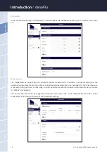
The web interface can now be accessed with any browser using the following URLs:
http://nanoFlu/ or
http://nanoflu_DXXX/ (DXXX is the serial number) or
http://192.168.77.1/
If the web interface cannot be accessed, make sure that the LAN cable was connected after
the sensor was connected to the power supply and try all three URL options.
Automatic measurement by the nanoFlu is stopped when an Ethernet-capable device is
connected. As soon as the LAN connection between the sensor and the Internet capable
device is disconnected, the measurements will be continued at the set interval if the timer is
activated.
Содержание nanoFlu
Страница 1: ...nanoFlu OPERATING INSTRUCTIONS ...
Страница 2: ......

