background image


3

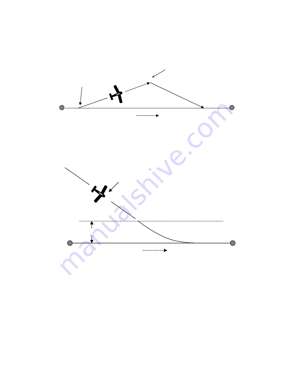
2.  Course mode (CRS)


– provides vector navigation as illustrated below.  

CRS

 also 

allows tracking an autopilot-selected course when the host GPS route function is not in 
use.  

CRS

 mode uses the GPS signal to provide the aircraft groundtrack.  This mode can 

be useful for avoiding restricted airspace, weather and oncoming air traffic. 


3.  Intercept mode (INT

)


– 

used to intercept a predefined GPS desired track (

DTK

) as 

illustrated below.  The 

INT

 mode also uses the GPS signal to provide the aircraft 

groundtrack.  This mode is useful to regain the original flight plan track after 
circumnavigating the previously mentioned flight obstacles.


In both the 

CRS

 and 

INT

 modes the ground track to be followed may be selected by the pilot, 

using either the L/R switch or the PCS steering mode of operation   
 
The EZ Pilot will automatically switch from the 

INT

 mode to the 

TRK

 mode as it nears the 

intercept boundary.    


Original GPS course line 

Intercept Boundary 

Variable distance depending on speed

X

Autopilot flies INT mode to intercept GPS course


As the aircraft nears the  GPS course line 
the autopilot automatically switches to 

TRK


WPT

WPT

GPS course line

X

Autopilot flies 

INT


WPT WPT 

Pilot commands 

CRS

 mode 

Pilot commands 

INT

 mode “intercept” 

Autopilot intercepts original course 

Содержание EZ PILOT

Страница 1: ...EZ PILOT Operation and Installation Manual Trio Avionics Corporation Rev 1 9 ...

Страница 2: ...for use as an en route navigation aid only and only at safe altitudes in unobstructed airspace It must not be relied upon for any other purpose It is not to be used for flight in instrument meteorological conditions IFR or approaches into airports in either IFR or visual VFR conditions Power to the servo must be turned off for takeoffs and landings In operation this product relies upon data provid...

Страница 3: ... 9 2 ETE Estimated Time En route HH MM 9 3 2 9 3 ETe Estimated Time En route MM SS 10 3 2 9 4 RNG Range to Waypoint 10 3 2 9 5 Waypoint 10 3 2 9 6 Digital Turn Coordinator Display 10 3 2 9 7 DIS 10 3 2 9 8 TRN 11 3 2 9 9 SPD 11 3 2 10 CRS Course Mode 11 3 2 11 INT Intercept Mode 12 3 2 12 TOP Track Offset Position 12 3 2 13 Automatic Course Reversal 13 3 2 14 Variable Display Field Upper Line 14 3...

Страница 4: ...6 3 Servo Direction Reversal 30 7 6 4 Servo Neutral Setting 30 7 7 In Flight Adjustment of Servo Neutral 30 7 8 System Optimization Flight Time Distance Counters and Totalizers 31 7 8 1 System Optimization 31 7 8 2 Flight Time Distance and Totalizer Counters EZ Pilot II only 33 7 8 2 1 Flight Time and Distance Counters 33 7 8 2 2 Flight Time and Distance Totalizer Displays 34 8 0 Electrical Requir...

Страница 5: ...r you and how to employ its three basic modes of navigation Section 3 is a detailed description of the Control and Display unit which will familiarize you with switch functions and the wealth of information available to you on the alphanumeric display Section 4 is a detailed description of the Setup Screens available to you to configure the autopilot to meet your preferences and the flight dynamic...

Страница 6: ...ccepts either a NMEA 0183 V2 XX stream format or the Aviation Link format for navigation guidance While the EZ Pilot is an excellent wing leveler it finds its greatest strength following a flight plan that is active on a host GPS This can be as simple as a GOTO command on the GPS or a complex multi segment flight plan Three navigation modes are provided that allow the pilot to follow a selected GP...

Страница 7: ...e original flight plan track after circumnavigating the previously mentioned flight obstacles In both the CRS and INT modes the ground track to be followed may be selected by the pilot using either the L R switch or the PCS steering mode of operation The EZ Pilot will automatically switch from the INT mode to the TRK mode as it nears the intercept boundary Original GPS course line Intercept Bounda...

Страница 8: ...In this condition the autopilot may still be used to provide a wing leveler function and the L R switch can be used to initiate turns to the left or right Once GPS data is present and validated full navigation function is available Servo power is initially off on power up The Servo Power Switch must be pressed momentarily to activate the system servo for either normal navigation or wing leveler fu...

Страница 9: ...y Data Fields The DISPLAY switch selects what data is presented on the variable fields of the display Momentarily pressing bumping the display switch advances the lower right line variable display field through the available selections Pressing and holding the display button then toggling the L R switch advances the upper right variable display field through its display selections see function 5 b...

Страница 10: ... SETUP mode function In this mode the following screens and operating parameters can be changed Contrast adjust LCD model only Servo position Remote dim or mode setting Turn rate selection AUTO or a fixed turn rate from 1 to 3 deg sec Last waypoint circle Rate of turn display LARGE or SMALL EZ Pilot II only Start up screen programming user programmable System Configuration screen factory software ...

Страница 11: ...exed i e they use the same display space to present different information This allows the pilot to view all navigation parameters including digital rate of turn information The display example shows the normal power up default display with GPS data present 3 2 1 Power up Display When the EZ Pilot is powered on a logo display is present showing the firmware revision operating in the unit This can b...

Страница 12: ...ke control of the roll axis of the aircraft 3 2 6 TRK Mode BTW Bearing To Waypoint Field The bearing to waypoint BTW field is located on the left side of the top line as illustrated This field is updated whenever the GPS data to the EZ pilot is refreshed normally once every one or two seconds depending on the GPS interface data rate A GPS with NEMA data output normally updates once every two secon...

Страница 13: ... closure speed to the destination waypoint ETE estimated time en route in hours and minutes format ETe estimated time en route in minutes and seconds format RNG distance from the current TO waypoint WPT TO waypoint identifier TC Digital graphic turn coordinator display DIS Distance tolerance error indicator TRN Turn tolerance error indicator SPD Speed tolerance error indicator TOP Track Offset Pos...

Страница 14: ...ld is limited to a maximum value of 999 miles 3 2 9 5 Waypoint The waypoint identifier currently programmed as the TO waypoint is presented in this field Up to six alphanumeric characters are available for this data field allowing for intersection and user waypoint identifications This field will flash at a 2 PPS rate for approximately 10 seconds when past the last waypoint in the route or past th...

Страница 15: ...ator RNG GS XTK TOP and ETE e fields are sequenced in the display at a 2 5 second rate This can be useful for sequentially monitoring all the parameters put out by the GPS without having to manually select each parameter 3 2 10 CRS Course Mode Assuming the TRK mode is currently selected the CRS course mode is entered by pressing the MODE pushbutton momentarily The mode is announced when the TRK LE...

Страница 16: ...led description of this feature The INT mode automatically establishes an approximate 25 degree intercept angle default setting toward DTK The commanded intercept course can be adjusted in the same manner as in the CRS mode using the L R switch or the PCS mode The INT mode is automatically cancelled and the TRK mode is entered when the aircraft crosses the intercept boundary line NOTE If SERVO POW...

Страница 17: ...d Press and hold the MODE button for three seconds That s all you need to do After three seconds the following will occur The servo will be energized if off and the wing leveler function will engage The upper right display line will read TRN 180 The lower right display line will be forced to the turn coordinator display A 175 degree right course reversal will be executed The display screen will ch...

Страница 18: ... Pilot No pilot action is required Normal TRK mode tracking computations are inhibited until the GPS data integrity is restored 4 0 Setup Screens The EZ Pilot provides a quick and easy method to set up certain parameters that are normally only changed at installation The setup mode allows adjustment of the following items 1 LCD contrast LCD model only 2 Setting of the initial servo position mechan...

Страница 19: ...0 knots but as speed increases the bank angle must be increased to achieve the standard rate of turn In faster aircraft this steeper bank may be uncomfortable to some pilots and indeed may exceed the capability of an altitude hold system to maintain altitude properly in the turn To remedy this the EZ Pilot has a means whereby the users can adjust the maximum rate of turn to their personal satisfac...

Страница 20: ... the maximum turn rate that you desire simply press the MODE switch again to select the next setup screen 4 4 IO DIM or MODE Screen There is provision for a remote DIM or remote MODE to be employed with the EZ Pilot The factory default is to use this button as a REMOTE DIM function to adjust the display brightness The user has the option to select the J1 Pin 1 input as either a REMOTE DIM function...

Страница 21: ...aracter position on line 1 MODE switch Terminates writing to the screen and advances to the next display screen NOTE The characters are written to non volatile memory as each character is changed If you accidentally sequence out of this screen or turn off power whatever information that was present on the screen at that time will be retained in memory 4 8 Software Configuration and Serial Number T...

Страница 22: ... receivers even though they have obtained satellite lock do not put out valid NMEA or AVLINK data until a flight plan or GO TO waypoint is entered or a preset groundspeed is attained usually 2 to 5 kts In this case either the NO GPS message or the NO FPLAN mode will be displayed Some GPS receivers output data are capable of providing groundtrack and groundspeed information to the EZ pilot after sa...

Страница 23: ...e the pilot engages the servo after takeoff and climb to safe altitude The EZ Pilot then intercepts and flies the course line DTK to the first waypoint During the flight on this leg some other navigation parameters are available for review such as estimated time to the waypoint ETE or ETe Pressing the DISPLAY switch presents this data Pressing the DISPLAY button again shows RNG distance to this wa...

Страница 24: ...ccomplished in one of two ways 1 The CRS mode is selected by pressing the MODE pushbutton momentarily or the optional remote mode pushbutton The following changes in the display are noted The TRK LED extinguishes the CRS LED is illuminated The BTW field changes to CRS The TRK field changes to 010 The CRS and TRK fields are for the moment identical 010 Since the controller wants 040 degrees formerl...

Страница 25: ...ck commanded in the INT field The IDS value is steadily decreasing toward zero After a short interval the TRK and INT values are approximately the same indicating a steady intercept track If it is desired to change the default intercept angle 25 degrees the pilot may engage the PCS MODE see Section 5 6 by pressing the Remote Servo Disconnect switch and manually flying the aircraft to the desired i...

Страница 26: ...g the pilot full control of the aircraft After the button is held down for 5 seconds or more the Servo LED will begin to flash indicating that the servo will re engage when the button is released This allows the pilot to manually orient the aircraft to the desired course and re engage the servo when the button is released ...

Страница 27: ...rve normal flight data similar to that shown in earlier pages of this manual 6 1 Your GPS If you do not get a proper display once your GPS is turned on and has a clear view of the sky check the wiring connections between the GPS unit and the EZ Pilot The signal input requires a data input and a ground and these must be wired as shown in the wiring diagram Section 8 6 Although GPS receivers general...

Страница 28: ...enna has a clear view of the sky in all directions at all normal flight attitudes 4 Some GPS units will not yield a serial output until a flight plan or Go To is entered and NO GPS will be displayed until this is accomplished Some other GPS receivers output only a few of the parameters needed for autopilot operation which the EZ pilot will recognize by entering the NO FPLAN mode Other receivers KI...

Страница 29: ...he control surfaces to move In the event of strong turbulence or an autopilot anomaly the pilot can thus override the servo to control the airplane In such an instance the servo should be disengaged as soon as possible NOTE The clutch function does not rely on a shear pin failure mechanism as is employed on some other popular autopilot servos Activation of the clutch function in no way damages the...

Страница 30: ... that allows full aileron movement aileron stop to aileron stop without driving the servo crank arm into its limits 50 degrees Most aircraft get best performance in the 3rd or 4th outermost hole 7 2 Servo Mounting Hardware A hardware mounting kit is shown below A hex shaped rod is provided with two rod end bearings attached Typically one of these connects to the servo crank arm and the other is st...

Страница 31: ... the case mounting tabs and then secure the assembly into place Once the assembly complete the servo base mounting tabs will fit down over the screws Nuts can be tightened down to secure it The long screws shown allow the servo to be raised and lowered simply by putting additional nuts on them so the servo is elevated above the plate For a composite aircraft installation the bottom of the plate sh...

Страница 32: ...trol stick or control wheel in all four corners to test this 7 5 Setting Servo Override Force Slip Clutch The servo Torque Control nut the locknut inside the servo on the output shaft sets the override force the force you will feel at the stick when the servo clutch begins to slip Engage the servo by pressing the SERVO button on the control head You should hear the solenoid operate inside the serv...

Страница 33: ...is critical to flight safety and proper autopilot operation If this is not set correctly the autopilot will not track correctly and will cause the airplane to roll to bank angles in excess of 30 degrees either right or left when the servo is engaged This setting cannot be changed in flight so it is critical that this be set correctly during ground setup and testing The numbers that appear in the r...

Страница 34: ...g data to the autopilot and the airplane is properly trimmed using the aircraft roll trim so that there is no tendency to roll off to the right or left Turn the autopilot off then back on while pressing and holding the DISPLAY button Release the DISPLAY button and then press the SERVO button to engage the servo If the aircraft tends to turn to the right with the servo on disengage the servo and pu...

Страница 35: ...ck centerline It has no effect outside of 07 miles 3 PULL IN Pull In controls system response when the aircraft is outside of the 07 miles crosstrack error or showing greater than 5 degrees of error to the selected course These settings should normally have to be set up only once during your first test flight To adjust the settings it is necessary to enter the Calibration Menu as follows Press the...

Страница 36: ...NE CRS QLT setting by two counts original count minus one 8 Repeat steps 3 to 7 until best tracking is obtained Normally the EZ Pilot will hold the groundtrack within 1 degree in smooth air You should then adjust the FINE TRK QLT for best performance while in the Track mode To do this you must first exit the calibrations screens back to the normal autopilot functions Here you should place the auto...

Страница 37: ...screens within the calibration displays menu 7 8 2 1 Flight Time and Distance Counters The Flight time and Flight distance counters on the first display screen and count the time of flight and flight distance as long as a speed of 50 knots or above is maintained This means that the flight and distance counters do not include time and distance information in the pre or post flight regimes These cou...

Страница 38: ...sed for the input power to pin 13 Additional ground wires are required to supply the current return path for other EZ Pilot signals 8 2 Servo Power The EZ pilot is capable of switching up to 5 amps of DC power to the EZ Pilot servo The current servo design draws less than 1 amp max under heavy load conditions The roll servo power is supplied to J1 pin 19 and the switched power to the servo is avai...

Страница 39: ...onnect 26 data momentary ground 15 airframe ground 24 power ground 2 16 spare 26 data 17 roll servo PWM out 26 data shielded wire required 1 18 reserved 19 roll servo power input 24 power power to roll servo 3 20 reserved 21 reserved 22 reserved 23 reserved 24 reserved 25 roll servo power output 24 power switched power to roll servo Notes 1 These signals should be run in a shielded cable along wit...

Страница 40: ...e desired track LED Light Emitting Diode L R Left Right MM SS Minutes Seconds NMEA 0183 Specification for GPS output data generally hand helds PCS Pilot Controlled Steering PWM Pulse width modulation the signal that drives the servo Servo Deflects ailerons as required by EZ Pilot TC Digital graphic turn coordinator display TRK Mode Track mode Autopilot tracks a preprogrammed GPS flight plan TRK Tr...

Отзывы: