


TMCM-610 Hardware Manual (V1.14/2010-APR-30)
8
Copyright © 2010, TRINAMIC Motion Control GmbH & Co. KG
4.2.1
Power supply
Connect a power supply of max. 34V DC here (the minimum operating voltage is 7V). The device is protected
against wrong polarity by a diode that shorts the power supply when the polarity is wrong.
The onboard connector is a RIACON type 219 two pole connector, fitting mate is for example a RIACON type 249
(see
4.2.2
LED indicators
There are two LEDs on the board. The right LED (
Power
, on a rev. 1.0 board marked with
+5V
) lights up when the
unit is powered. The other LED (
Activity
, on a rev. 1.0 board marked with
D101
) flashes when the unit is running
normally.
4.2.3
Motor connectors
The stepper motors can either be connected to the screw terminals or to the connectors behind the screw
terminals. They are electrically identical. The pin assignments of the connectors are printed on the board. Connect
one coil of the motor to the terminals marked
A0
and
A1
and the other coil to the connectors marked
B0
and
B1
.
See
Never connect or disconnect a motor while the unit is powered! This may damage the motor drivers and / or
other parts of the unit!
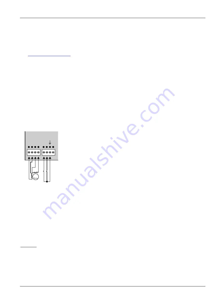
A
0
A
1
B
0
B
1
R L
+5
V
Motor 0 Ref 0
M
Figure 4.3: Motor and reference switch connection
4.2.4
Stop switches / reference switches
The stop switches can be connected to the
terminals
marked
L
and
R
and to the GND terminal. The switches are
normally closed
.
The reference switch connectors also have a
+5V
terminal
. This is a 5V output that can be used to supply photo
couplers or digital hall sensors.
The left stop switch is also used as the reference switch.
Attention:
On the version 1.0 of the board the stop switch connectors are marked wrongly (L and R have been interchanged)
.
So, on a version 1.0 board, connect the left stop switch to the terminal marked with
R
and the right stop switch to
the terminal marked with
L
.
The marking is corrected on the next version of the board.