


TMCM-3351 Hardware Manual • Hardware Version V1.00 | Document Revision V1.00 • 2017-SEP-01
14 / 31
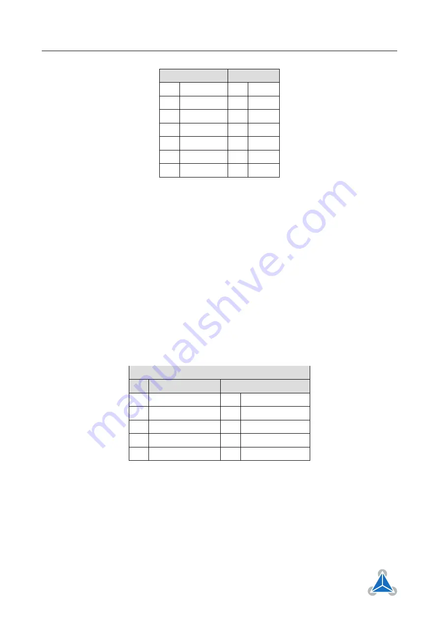
Pin Label
Pin Label
7
OUT_6
8
OUT_7
9
+5V_output
10
GND
11
IN_0
12
IN_1
13
IN_2
14
IN_3
15
IN_4
16
IN_5
17
IN_6
18
IN_7
19
/Shutdown
20
VDD
Table 14: I/O Connector
The /Shutdown input pin has to be connected to the supply voltage in order to enable the driver stages
for all three stepper motor axes. A jumper between pin 19 and pin 20 can be used to permanently enable
drivers (please refer to section
for more detailed information).
4.11 Encoder Connector
Three encoder connectors (one dedicated encoder interface and connector per axis) are available. A
standard 2.54mm pitch two row header is used for encoder connection. Incremental a/b/n encoder with
differential or single ended (push-pull TTL or open-drain) output signals are supported.
For encoder with single ended output signals the non-inverting inputs of the encoder connector should
be used (A+, B+ and N+). Please do not activate encoder line termination for single ended encoder signals
(remove jumpers). Refer to section
for more details.
For encoder with differential output signals the non-inverting and inverting signal pairs should be con-
nected (A+ and A-, B+ and B-, N+ and N-) and on-board line termination might be activated (setting jumpers
- refer to secton
for more details).
Incremental encoders with +24V push-pull output signals are not supported. Please use appropriate in-
terface circuits for these types of encoders.
Encoder Connector
Pin
Label
Pin
Label
1
GND
2
GND
3
Encoder_0/1/2_N+
4
Encoder_0/1/2_N-
5
Encoder_0/1/2_A+
6
Encoder_0/1/2_A-
7
+5V_output
8
+5V_output
9
Encoder_0/1/2_B+
10
Encoder_0/1/2_B-
Table 15: Encoder Connector
©2021 TRINAMIC Motion Control GmbH & Co. KG, Hamburg, Germany
Terms of delivery and rights to technical change reserved.
Download newest version at


