


PD-013-42 / TMCM-110-42 Manual (V1.24/2011-NOV-25)
24
Copyright © 2011, TRINAMIC Motion Control GmbH & Co. KG
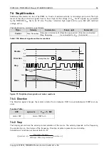
8.4
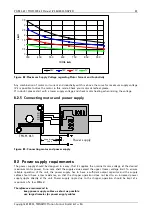
Connections for step/direction mode
The step-direction-mode is enabled if the acceleration is set to 0 (default) using the RS485. The example
input signals of Figure 8.4 are schematically (see chapter 5.1 for more information):
5 ... 28 V
Disable
Common
0 V
rotation on off
at Vcommon or left open
Step
Common
0 V
Velocity Deceleration Acceleration
const.
Dir
Common
0 V
rotating direction
Dir
Common
Disable
Step
PWR 7...28 V
TMCM-013
Pin 1
Pin 2
Pin 3
Pin 4
Pin 5
Pin 6
Figure 8.4: Contacts for step/direction
The maximum step frequency is 350 kHz (limited by the optocouplers).
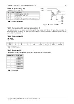
8.5
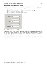
Connections for RS485 interface
The RS485 mode allows for configuration of motor parameters as well as remote control of the motor.
8.5.1
Interface installation
To connect the module to a PC a RS485 interface is required, for example TRINAMICs USB-2-485 or any other
RS485 adapter like standard RS232 to RS485 converters. Input
A
has to be connected to pin 15 of the TMCM-
013 and Input
B
to pin 16.
R
S23
2
to
R
S48
5
4 3 2 1
U
SB
to
R
S48
5
+
-
Pin 1
Pin 2
TMCM-013
RS-232-port
USB-port
Terminal
PWR 7...28 V
Pin 14
Pin 15
Pin 16
GND
optional
Either use a RS232 to RS485
or alternatively
a USB to RS485 adapter
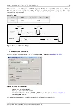
Figure 8.5: Contacts for RS485 with an adapter


