


IDX 7505 Manual (V1.17 / 2011-APR-11)
29
Copyright © 2011, TRINAMIC Motion Control GmbH & Co. KG
Internally the current is regulated by two independent parameters for the best module/motor
performance possible.
For chopper mode 2, the maximum setting is about 75% to 90% - at higher settings, motor microstep
behavior may become harsh. The actual maximum depends upon the actual motor. This is to avoid
the motor coil current raising above the 100% setting at any time. Not all currents can be
continuously driven at all supply voltages / cooling circumstances.
Please refer to motor current
limitations.
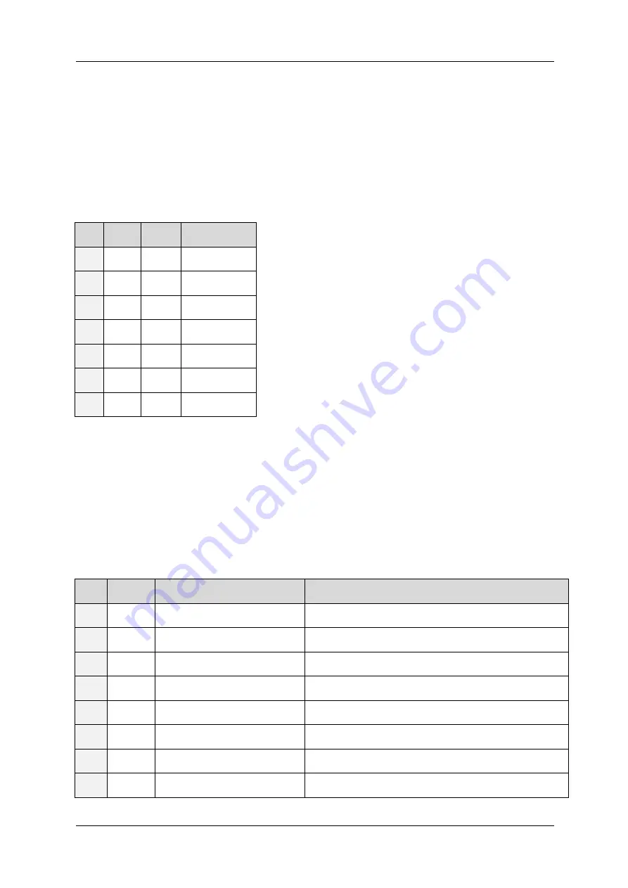
AC I
COIL,PP
I
COIL,RMS
% to max. I
COIL
100 7.1A 5.0A
100% *)
75 5.3A 3.8A
75%
66 4.7A 3.3A
66%
50 3.5A 2.5A
50%
33 2.4A 1.7A
33%
25 1.8A 1.26A
25%
10 0.71A 0.50A
10%
Table 7.2: Motor Current Examples for IDX
*) except chopper mode 2
7.2.1.3
Failure readout (E)
The IDX provides a full driver failure analysis in SPI mode (8 Bit). The returned bit assignments are as
follows:
Bit
Name
Function
Remark
7 OT
overtemperature
1 = driver chip off due to overtemperature
6 OTPW temperature pre-warning
1 = driver chip prewarning temperature exceeded
5 UV
driver undervoltage
1 = undervoltage on VS – does not cover all cases
4 OCHS
overcurrent high side
(not available in current hardware implementation)
3 OLB
open load bridge B
Open load detection can occur at fast motion also.
2 OLA
open load bridge B
Open load detection can occur at fast motion also.
1 OCB
overcurrent bridge B low side Short circuit detected. Please check motor wiring.
0 OCA
overcurrent bridge A low side Short circuit detected. Please check motor wiring.
Table 7.3: Failure readout in SPI mode


