background image

innovative technology

 to keep you a 

step ahead

www.trilithic.com

Copyright ©  2016 Trilithic, Inc. All Rights Reserved - 071316-REV2 

Specifications are subject to change without notice. Please contact your sales representative for further information.  
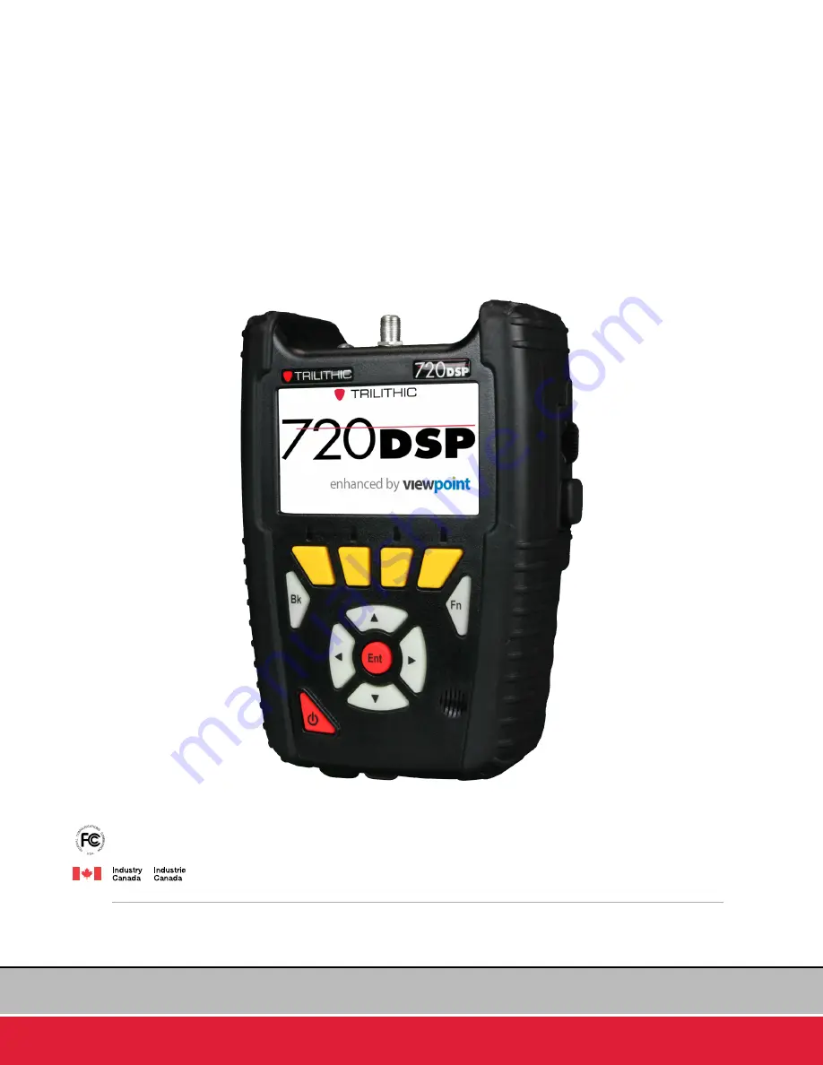
720 DSP 

Business Certification Meter

Operation Manual

This equipment has been tested and found to comply with the limits for a Class B digital device, pursuant to Part 15 of the FCC Rules. 

See Page iv for complete details.

This Class B digital apparatus complies with Canadian ICES-003. See Page v for complete details.

The CM Sweep feature is patent pending.

Содержание 720 DSP

Страница 1: ... sales representative for further information 720 DSP Business Certification Meter Operation Manual This equipment has been tested and found to comply with the limits for a Class B digital device pursuant to Part 15 of the FCC Rules See Page iv for complete details This Class B digital apparatus complies with Canadian ICES 003 See Page v for complete details The CM Sweep feature is patent pending ...

Страница 2: ...www trilithic com Page ii 720 DSP Operation Manual THIS PAGE LEFT INTENTIONALLY BLANK Business Services Meter ...

Страница 3: ...o managing change helping customers respond quickly to market opportunities with innovative technology and individualized solutions But the core value of Trilithic s business approach listening to customers hasn t changed Keeping that focus intact will help provide better products in the long run and ensure continued growth for decades to come Trilithic is comprised of two major divisions Broadban...

Страница 4: ...ment is installed at the Trilithic factory or by Trilithic approved repair facilities During operation of the device a distance of 20 cm or more should be maintained between the antenna in this device and any persons and must not be co located or operating in conjunction with any other antenna or transmitter To ensure compliance do not operate at closer distances than this The antenna on the 720 D...

Страница 5: ...et appareil doit accepter tout brouillage y compris celui pouvant causer un mauvais fonctionnement de l appareil Cet appareil numérique de classe B est conforme à la norme canadienne ICES 003 Industry Canada Compliance This device complies with Industry Canada license exempt RSS standard s Operation of this device is subject to the following two conditions 1 This device may not cause harmful inter...

Страница 6: ...www trilithic com Page vi 720 DSP Operation Manual THIS PAGE LEFT INTENTIONALLY BLANK Business Services Meter ...

Страница 7: ...e 720 DSP I 9 Overview I 9 The Standardization Solution I 9 Gigabit Ethernet Testing I 9 Next Generation Features I 10 Simple Yet Powerful I 10 Autotest Apps I 10 Justify ROI I 11 Total System Management I 11 Standard Interfaces I 12 Standard Testing Features I 12 Advanced Measurement Functions I 12 Frequency Domain Reflectometer I 12 Forward Spectrum Analysis I 13 Upstream Linear Distortions Meas...

Страница 8: ...1 Protective Carrying Case I 22 Optical Transceiver Installation Removal I 23 Cleaning the Display Screen I 24 Battery Charging I 25 Charging Status I 25 Basic Navigation Control I 26 Startup I 26 Sleep Mode I 27 Automatic Sleep Mode I 27 Manual Sleep Mode I 27 Wake from Sleep Mode I 27 Shutdown I 28 Automatic Shutdown I 28 Manual Shutdown I 28 Display Screen I 29 Title Bar I 29 Message Bar I 29 M...

Страница 9: ... 100 Mbps I 42 Wi Fi Connection I 43 Gigabit Ethernet Connection 10 100 1000 Mbps I 45 Bluetooth Connection OPTIONAL I 47 DOCSIS Cable Modem to Ethernet Connection I 50 Log Off User I 53 Chapter 5 Remote Access I 55 Accessing the 720 DSP Remotely I 55 Section II Setup Menu II 1 Chapter 1 Overview II 3 Introduction II 3 Chapter 2 Instrument Information II 5 Overview II 5 Version Information II 6 Ca...

Страница 10: ...Control II 16 Auto Start Network II 16 Language II 17 Measurement Units II 17 Current Date Time II 18 Timezone II 19 User Settings II 20 User Name II 21 Company II 22 Tech ID II 23 Interface Settings II 24 LCD Dimming Delay II 25 Sleep Mode Delay II 26 Turn Off Delay II 27 Flashlight Delay II 28 Keypad Beeps II 28 Keypad Delay II 29 Keypad Rate II 29 Temperature Units II 30 Distance Units II 30 Jo...

Страница 11: ...annel Properties II 45 Center Frequency II 45 Analog Channel Properties II 46 Channel Standard II 46 Center Frequency II 47 Bandwidth II 48 Video Frequency II 49 Audio Frequency II 50 Scrambled II 50 Digital Channel Properties II 51 Channel Standard II 51 Center Frequency II 52 Bandwidth II 53 Modulation II 54 Symbol Rate II 54 DOCSIS II 55 Channel Presets II 55 Save an Open Channel Plan II 56 Sav...

Страница 12: ...User II 73 Bypass IP II 73 Certificate II 74 Primary Frequency II 74 DOCSIS Mode II 75 Annex Mode II 75 Upstream ID II 76 Level Correction II 77 Wi Fi Settings II 78 Prompt User II 78 Current SSID II 79 Current Password II 80 Current Security II 81 Select Default Access Point II 82 Delete a Saved Access Point II 83 Bluetooth Settings OPTIONAL II 84 Prompt User II 84 Gigabit Ethernet Settings II 85...

Страница 13: ...mport ViewPoint Files from a USB Flash Drive II 101 Export a File II 103 Export All Files II 105 Delete Files II 107 Delete Web Browser Cookies Cache II 108 Save Log File II 109 Save to Internal Memory II 109 Save to USB Flash Drive II 110 Function Menu Options II 111 Activate USB Power II 111 Deactivate USB Power II 111 Chapter 5 Touchscreen Calibration II 113 Overview II 113 Disable Touchscreen ...

Страница 14: ...ViewPoint Sync III 7 Chapter 3 Job Management III 9 Overview III 9 Create a New Job III 10 Close an Open Job III 11 Open a Closed Job III 12 Delete an Existing Job III 13 Function Menu Options III 14 Changing Channel Plan of an Existing Job III 14 Changing Comments of an Existing Job III 15 Chapter 4 Using Autotests III 17 Overview III 17 Location Pass Fail Indicators III 19 Executing an Autotest ...

Страница 15: ...al Scale Adjustment IV 12 Channel Adjustment IV 12 Video Frequency Adjustment IV 13 Audio Frequency Adjustment IV 14 Display Type Adjustment IV 15 Bar Graph IV 15 HUM IV 16 Go to Spectrum IV 17 Go to Scan IV 18 Digital Channel Measurement IV 19 Reference Level Adjustment IV 20 Vertical Scale Adjustment IV 21 Channel Adjustment IV 21 Digital Video Frequency Adjustment IV 22 Channel Bandwidth Adjust...

Страница 16: ... IV 36 Go to Spectrum IV 37 Go to Scan IV 38 Function Menu Options IV 39 Save Data Log IV 39 Test Point Compensation IV 41 Test Point Loss IV 41 Probe Loss IV 42 Save Preset IV 43 Load Preset IV 44 Auto Range IV 45 Chapter 3 Channel Plan Scan IV 47 Overview IV 47 Opening a Channel Plan IV 48 Opening a Limit Set IV 49 Removing a Limit Set IV 50 Pass Fail Measurement Indicators IV 51 Display Type Ad...

Страница 17: ...rement IV 65 Overview IV 65 Opening a Channel Plan IV 66 Opening a Limit Set IV 67 Removing a Limit Set IV 68 Pass Fail Measurement Indicators IV 69 Display Type Adjustment IV 70 Measurement Results IV 70 Full View IV 70 Text View IV 70 Reference Level Adjustment IV 71 Vertical Scale Adjustment IV 71 Tilt Measurement Marker Adjustment IV 72 Function Menu Options IV 73 Save Data Log IV 73 Hide Mark...

Страница 18: ...0 Hide Marker Bar IV 92 Test Point Compensation IV 93 Test Point Loss IV 93 Probe Loss IV 94 Forward Spectrum Measurement IV 97 Reference Level Adjustment IV 98 Vertical Scale Adjustment IV 99 Start Frequency Adjustment IV 99 Stop Frequency Adjustment IV 100 Center Frequency Adjustment IV 101 Span Frequency Adjustment IV 102 Marker Adjustment IV 103 Detector Type IV 104 Maximum IV 104 Average IV 1...

Страница 19: ...123 Upstream Channel Adjustment IV 123 Marker Adjustment IV 124 Tap Markers IV 124 Spectrum Markers IV 124 Chapter 8 Network Test Suite IV 125 Overview IV 125 Selecting the Test Mode IV 126 Setting the Destination IP Address IV 127 Selecting a Favorite IV 128 Executing Network Tests IV 128 Ping Mode IV 129 Setting the Number of Packets IV 130 VoIP Mode IV 131 Throughput Mode IV 132 Setting the Tar...

Страница 20: ...ts IV 160 Loopback Mode IV 164 SFP Optical Power Meter IV 167 Function Menu Options IV 168 Configure Interface IV 168 Chapter 10 Frequency Domain Reflectometer IV 169 Overview IV 169 Reference Level Adjustment IV 170 Velocity of Propagation Adjustment IV 171 Marker Adjustment IV 172 Chapter 11 QAM Error Vector Spectrum Analysis OPTIONAL IV 173 Overview IV 173 Reference Level Adjustment IV 174 Chan...

Страница 21: ...Settings IV 187 Measurement Mode IV 187 Chapter 13 Cable Modem Sweep OPTIONAL IV 189 Overview IV 189 Using CM Sweep IV 190 Modem Quality of Service IV 192 Section V Utility Menu V 1 Chapter 1 Overview V 3 Introduction V 3 Chapter 2 Web Browser V 5 Using the Web Browser V 5 Chapter 3 Wi Fi Access Point Survey V 7 Performing a Wi Fi Access Point Survey V 7 Choose Display Type V 8 View Sort V 8 ...

Страница 22: ...ctivation Deactivation V 15 Section VI Appendix VI 1 Chapter 1 Specifications VI 3 Level Measurement VI 3 Spectrum Measurement VI 4 Digital Channel Measurement VI 4 Cable Modem Measurement VI 5 Carrier to Noise Measurement VI 6 Tilt Measurement VI 6 HUM Measurement VI 6 Source Generator OPTIONAL VI 7 QAM Source VI 7 CW Source VI 7 Physical Specifications VI 8 Available Interface Types VI 9 Battery...

Страница 23: ...www trilithic com 720 DSP Business Certification Meter Section I The Basics ...

Страница 24: ...www trilithic com Page I 2 720 DSP Operation Manual THIS PAGE LEFT INTENTIONALLY BLANK Business Services Meter ...

Страница 25: ...is available Monday through Friday from 8 00 AM to 5 00 PM EST Callers in North America can dial 1 317 895 3600 or 1 800 344 2412 toll free International callers should dial 1 317 895 3600 or fax questions to 1 317 895 3613 You can also e mail technical support at support trilithic com For quicker support response when calling or sending e mail please provide the following information Your name an...

Страница 26: ...w of the instrument and its basic features Before using the instrument it is recommended that the user read this section for an overview of features basic commands and other important details Section II Setup Menu This section includes instructions on how to use the features shown in the Setup Menu of the instrument Section III Autotest Menu This section includes instructions on how to use the fea...

Страница 27: ... menus menu options and user entered text and commands appear in bold Section names web and e mail addresses appear in italics A CAUTION alerts you to any condition that could cause a mechanical failure or potential loss of data A NOTE is information that will be of assistance to you related to the current step or procedure A WARNING alerts you to any condition that could cause personal injury ...

Страница 28: ...r Pursuant to FCC 15 21 of the FCC rules changes not expressly approved by Trilithic might cause harmful interference and void the FCC authorization to operate this product The antenna used for this instrument is installed at the Trilithic factory or by Trilithic approved repair facilities During operation of the device a distance of 20 cm or more should be maintained between the antenna in this d...

Страница 29: ...nent damage by scratching the screen or stripping the anti glare coating off the screen Never use any type of window cleaner soap scouring powder or any cleanser with solvents such as alcohol benzene ammonia or paint thinner These chemicals can react with the materials used to construct the display which can lead to hazing yellowing brittleness or other types of damage DO NOT install the SFP trans...

Страница 30: ...ns limit sets and autotests Define meter settings Query display and delete test data ViewPoint Integrated Server Package with WFM Module ViewPoint Integrated Server Package with WFM Module is a server based software application with a web browser interface that supports advanced 720 DSP configuration and data management as follows Includes all of the features included in ViewPoint Express Server i...

Страница 31: ...thing needed for service business or residential installations Eliminate the need for multiple instruments in most business services with Gigabit Ethernet Throughput testing and save capital expenditures at the same time Tailored for the challenges faced by installers contractors and service techs this meter comes equipped with all of the powerful troubleshooting tools for the experienced tech yet...

Страница 32: ...data transmission Interactive autotesting apps Autotest Apps The 720 DSP features next generation autotest applications that practically walk the technician through a job By performing standardized measurement tests at various required locations on the job site using custom test plans channel plans and limit sets the meter very clearly indicates using color and symbols what areas still need attent...

Страница 33: ...s and the associated ROI Combining 720 DSPs in the field with the new ViewPoint WFM Module in the back office managers can view the health of their entire system in near real time for total installation service management Total System Management Combining the 720 DSP meter in the field with the new ViewPoint Integrated Server in the back office managers now have simplified access to intelligent ma...

Страница 34: ... Tilt Measurement Ping Trace Route VoIP Throughput Measurements Cable Modem Statistics Advanced Measurement Functions The 720 DSP includes all of the following advanced measurement functions standard Frequency Domain Reflectometer This feature enables the 720 DSP to provide a simple convenient and accurate tool for determining the distance to cable faults by sending a sweep into the cable and anal...

Страница 35: ...d hardware option package that is used to connect the 720 DSP to an iPad via Bluetooth for remote control of the meter during operation This package includes a software activation key for the BCA option on the 720 DSP and a Class II Mini Bluetooth Adapter v2 1 with a 10 meter range for speeds up to 3 Mbps This option is compatible with the iPad and iPhones that have device tethering enabled by the...

Страница 36: ...feature can be used to see impairments with ease and sort traffic from ingress within a bursty upstream CM Sweep When activated in a 720 DSP the CM Sweep feature patent pending provides users with the ability perform in band sweeps or upstream alignment without any headend sweep gear This feature can be used to balance the upstream see the percentage of pre equalizer effort and isolate problems be...

Страница 37: ...DSP The 720 DSP comes with the following 720 DSP Business Services Meter Two Built In Li Ion Batteries Protective Carrying Case with Shoulder Strap Touchscreen Stylus with Tether AC to DC Power Adapter Battery Charger AC US Power Cable Replacement Parts The following replacement parts are available for the 720 DSP Part Number Description 0090061000 Li ION Replacement Battery Replacement Requires 2...

Страница 38: ...uration Software for the 720 DSP 2011657000 ViewPoint Integrated Server with WFM Module for the 720 DSP 0930144000 ACTS software for high speed network testing Field Accessories The following accessories are available for the 720 DSP Part Number Description 2071527048 Precision test cable I O 15 2072097000A Vehicle Power Adapter 2131221000 Large Utility Carrying Bag 0190322000 AC Euro Power Cable ...

Страница 39: ...ulti mode transceiver 1000 Mbps LC connector and 550 meter reach 2072185004 SFP 1000 SX 1310 nm SFP single mode transceiver 1000 Mbps LC connector and 10 km reach 2072185005 SFP 1000 ZX 1550 nm SFP single mode transceiver 1000 Mbps LC connector and 80 km reach 2072191001 Six 6 foot multi mode optical patch cable full duplex with LC to LC connectors 2072191002 Six 6 foot single mode optical patch c...

Страница 40: ...8 720 DSP Operation Manual Business Services Meter A Guided Tour of the 720 DSP Front View RF Input Connector Touch Screen LCD Softkeys Back Button Arrow Buttons Power Button Enter Button Function Button Water Resistant Speaker ...

Страница 41: ...www trilithic com Page I 19 720 DSP Operation Manual Business Services Meter Rear View RF Input Connector Internal Wi Fi Antenna 2 dB Gain Identification Label S N FCC ID Notice ...

Страница 42: ...Wi Fi Antenna 2 dB Gain LED Flashlight Ethernet Port 10 100 Mbit s USB 2 0 Port Type A DC Charge Port System Reset Button Protective Rubber Door with Magnetic Closure In the image above the protective rubber door is in the open position for illustrative purposes This door should remain closed when not using any of these ports ...

Страница 43: ...ort 10 100 1000 Mbit s Protective Rubber Door with Magnetic Closure In the image above the protective rubber door is in the open position for illustrative purposes This door should remain closed when not using any of these ports Only one of the Gigabit Ethernet interface can be selected for testing both the Electrical and Optical port cannot be used simultaneously ...

Страница 44: ...der and adjustable Velcro hand strap Removable shoulder strap not shown Metal D rings for shoulder strap or line hook with reinforced stitching throughout Front flap with magnetic closure provides full access to the touchscreen keypad and bottom ports when open When the front flap is closed it provides protection to the touchscreen and keypad as well as the bottom ports Rear flap with Velcro closu...

Страница 45: ...ort on the right side of the 720 DSP Be sure to insert the optical transceiver with the SFP label facing the back of the device 3 Clean the fiber optic connectors on the fiber optic cables 4 Plug the appropriate fiber optic cable into the connector on the SFP module 5 To remove the optical transceiver first disconnect the fiber optic cable and then use the bail to pull the optical transceiver out ...

Страница 46: ...g cloth and then wipe the screen gently For correct cleaning of the display follow these four simple steps 1 Turn off the 720 DSP before you begin If the screen is dark it will be easier to see any areas that aren t clean 2 Very gently wipe the display with an ultrasoft clean lint free dry cloth If this does not completely clean the display DO NOT press harder on the screen in an attempt to clean ...

Страница 47: ...it defaults to the Fast Charge method Charging Status The Title Bar at the top of the 720 DSP screen displays the battery voltage and the following charging status icons Charging This icon is displayed when the 720 DSP battery is charging When charging the battery voltage will be shown between 12 and 14 VDC dependent on charging source 100 Charge This icon is displayed when the 720 DSP battery is ...

Страница 48: ...shown in the image above Use the touchscreen or keypad to select the user profile that you wish to use The Troubleshoot menu will be displayed as shown in the image to the right If multiple user profiles are deactivated the 720 DSP will automatically display the Troubleshoot menu as shown in the image to the right For more information about configuring multiple user profiles see Section II Setup C...

Страница 49: ...od of time The default setting for the sleep mode delay is 5 Minutes The sleep mode delay can be set from a minimum of one 1 minute up to a maximum of 60 minutes Manual Sleep Mode To manually enter the sleep mode quickly press the Power button Wake from Sleep Mode Quickly Press the Power button to wake the 720 DSP from sleep mode The sleep mode delay timer will automatically restart For more infor...

Страница 50: ...f delay is 1 Hour The turn off delay can be set from a minimum of one 1 hour up to a maximum of 24 hours Manual Shutdown Press and hold the Power button to shutdown the 720 DSP A notification window will be displayed select the OK button to shutdown or select the Cancel button to exit without shutting down the device For more information about setting the Turn Off Delay see Section II Setup Chapte...

Страница 51: ...he top of the display screen an example is shown in the image below The left side of the title bar displays the name of the currently selected screen such as the Autotest Troubleshoot Setup and Utility menus the right side of the Title Bar displays the battery voltage charging status date and time Message Bar The message bar is located below the main display area an example is shown in the image b...

Страница 52: ... If multiple user profiles are enabled the Welcome to the 720 DSP screen will always be displayed upon startup as shown in the image to the right After selecting a function icon from any navigation menu the measurements and data will be displayed in this area For example the image shown to the right represents the type of information that would be displayed in a measurement mode After selecting a ...

Страница 53: ...t Troubleshoot Setup and Utility softkeys Other Screens On measurement screens the softkeys are used to access additional measurement functions such as SETUP FUNCTIONS File Management New Open Save and Save As commands for Channel Plan Limit Set Channel Plan Management Add Remove and Preset commands Limit Set Management Remove command MEASUREMENT UTILITY FUNCTIONS Job Management New Open Close and...

Страница 54: ...on In the example images shown to the right notice how the currently selected item is highlighted blue and the other items remain gray Once you select an item you will either enter a new function or a window will appear If the touchscreen doesn t recognize your touch the location of the touch is inaccurate or it does not otherwise appear to be operating correctly it may need to be calibrated For m...

Страница 55: ...elect menu options from pop up menus Select channel plans and limit sets from file lists Arrow Buttons The arrow buttons are used to navigate highlight items scroll lists or change values on the display screen Back Button The Back button is used to take you back to a previous screen or to close a menu It can also be used to exit a pop up entry window without accepting entry information If you hold...

Страница 56: ...y a keyboard with lower case letters Select the ABC softkey to display a keyboard with upper case letters Select the 123 softkey to display a keyboard with numbers and symbols Select the 123 softkey to display a keyboard with additional symbols abc softkey selected ABC softkey selected 123 softkey selected 123 softkey selected To delete existing text use the Back softkey Once you have finished mak...

Страница 57: ...provide you with an understanding of the most common Function menu options as follows Pause Meter Toggle Flashlight Screen Capture Network Manager Log Off User Pause Meter This function is used to pause the meter during measurements To pause meter measurements select the Pause Meter function from the Function menu as shown in the image to the right The Title Bar will be highlighted in red and disp...

Страница 58: ...he Function menu as shown in the image to the right The LED flash light will illuminate until the flashlight delay has expired between 30 and 180 seconds user adjustable or it has been manually toggled off To manually toggle the LED flash light off press the Function button and then select the Toggle Flashlight function again To adjust the Flashlight Delay see Section II Setup Chapter 3 Meter Conf...

Страница 59: ... shown in the image to the right If you have an open job you can also save the screen capture to the job by selecting Yes as shown in the image to the right If you don t want to save the test to the open job select No and you will be prompted to enter a file name using the Virtual Keyboard It will then be saved to the internal memory of the 720 DSP To view the files saved to the internal memory of...

Страница 60: ...he RF Input Connector Ethernet This enables the built in 10 100 Mbit s Ethernet port on the bottom of the unit Wi Fi This enables Wi Fi communications via an internal Wi Fi antenna GigE This enables the built in 10 100 1000 Mbit s Ethernet Port on the right side of the unit Bluetooth This enables Bluetooth communications via an optional USB Bluetooth adapter Network Manager Before proceeding throu...

Страница 61: ...is currently inactive From any navigation menu the active connections are shown in the right side of the Status Bar as follows DOCSIS This symbol indicates the DOCSIS connection is currently active Ethernet This symbol indicates the 10 100 Ethernet connection on the bottom side of the device is currently active Wi Fi This symbol indicates the Wi Fi connection is currently active Bluetooth This sym...

Страница 62: ...button with an active status The Continue window will appear as shown in the image to the right Select the OK button to disconnect or select the Cancel button to exit without disconnecting Do not connect an RJ 45 cable to the Ethernet Port when the DOCSIS connection is enabled Otherwise the DOCSIS connection will not operate properly To use both connections at the same time follow the instructions...

Страница 63: ...tton 4 The Cable Modem Settings window will display the network connection progress as shown in the image to the right 5 The icon of the active connection will be displayed in the Message Bar 6 Return to the Network Manager window to view the MAC IP Subnet Gateway and DNS of the cable modem connection as shown in the image to the right A static IP of 192 168 100 2 will be assigned to the cable mod...

Страница 64: ... option of the Setup menu the Ethernet Settings window will appear as shown in the image to the right Adjust the Ethernet settings as desired and then select the Login button Do not connect an RJ 45 cable to the Ethernet Port when the DOCSIS connection is enabled Otherwise the DOCSIS connection will not operate properly To use both connections at the same time follow the instructions later in this...

Страница 65: ...e Network Manager window to view the MAC IP Subnet Gateway and DNS of the Ethernet connection as shown in the image to the right Wi Fi Connection Perform the following steps to connect using the Wi Fi connection 1 Select the Wi Fi connection button from the Network Manager window as shown in the image to the right If the Prompt User option is set to No from within the Wi Fi Settings option of the ...

Страница 66: ...will appear as shown in the image to the right Select the desired network from the list adjust the Wi Fi settings as needed and then select the Login button 4 The Wi Fi Settings window will display the network connection progress as shown in the image to the right 5 The IP address and icon of the active connection will be displayed in the Message Bar 6 Return to the Network Manager window to view ...

Страница 67: ...SP 2 Select the GigE connection button from the Network Manager window as shown in the image to the right 3 If the Prompt User option is set to Yes from within the GigE Settings option of the Setup menu the Ethernet Settings window will appear as shown in the image to the right Adjust the Ethernet settings as desired and then select the Login button If the Prompt User option is set to No from with...

Страница 68: ...window will display the network connection progress as shown in the image to the right 5 The icon of the active connection will be displayed in the Message Bar 6 Return to the Network Manager window to view the MAC IP Subnet Gateway and DNS of the Ethernet connection as shown in the image to the right ...

Страница 69: ...et to Yes from within the Bluetooth Settings option of the Setup menu the Bluetooth Settings window will appear as shown in the image to the right Adjust the IP and Subnet Addresses as needed and then select the Login button 5 The Bluetooth Settings window will display the network connection progress as shown in the image to the right 6 On the iPad select the name of the Trilithic Device from the ...

Страница 70: ...indow will display the network connection progress as shown in the image to the right 8 If the iPad that you are connecting to has never been paired with the 720 DSP a window will be displayed as shown in the image to the right 9 Once the 720 DSP connects to the iPad the Bluetooth Settings window will display the network connection progress ...

Страница 71: ...anual Business Services Meter 10 The icon of the active connection will be displayed in the Message Bar 11 Return to the Network Manager window to view the MAC IP Subnet Gateway and DNS of the Bluetooth connection as shown in the image to the right ...

Страница 72: ...Select the DOCSIS connection button from the Network Manager window as shown in the image to the right DOCSIS Cable Modem to Ethernet Connection If the Prompt User option is set to No from within the Cable Modem Settings option of the Setup Menu the Cable Modem Settings window will not appear If so proceed to Step 4 Do not connect an RJ 45 cable to the Ethernet Port until after the DOCSIS connecti...

Страница 73: ...s desired and then select the Login button 4 The Cable Modem Settings window will display the network connection progress as shown in the image to the right 5 The icon of the active connection will be displayed in the Message Bar 6 Press the Function button and select the Cable Modem to RJ45 function from the Function menu as shown in the image to the right If your cable modem system does not allo...

Страница 74: ...he Ethernet cable to the Ethernet Port of a PC 10 The 720 DSP should now be routing the cable modem data through the Ethernet Port to the connected PC To exit this function perform the following steps 1 Disconnect the Ethernet cable from the Ethernet port of the 720 DSP 2 Press the Back button to disable the cable modem to RJ45 mode 3 The Ethernet connection will automatically be disabled However ...

Страница 75: ... the Log Off User function from the Function menu as shown in the image to the right The Welcome to the 720 DSP screen will be displayed from this screen you can now log in as a different user If the Multiple Users option is set to No from within the Global Settings option of the Setup menu the Log Off User function and welcome screen will not be displayed ...

Страница 76: ...www trilithic com Page I 54 720 DSP Operation Manual THIS PAGE LEFT INTENTIONALLY BLANK Business Services Meter ...

Страница 77: ...t From this list select the function that you would like to perform as follows Remote Control This is used to display a web page with a control layout similar to the 720 DSP From this page you can control almost any function of the 720 DSP Log File This is used to display a web page that includes all of the information currently stored in the log file of the 720 DSP System Stats This is used to di...

Страница 78: ...www trilithic com Page I 56 720 DSP Operation Manual THIS PAGE LEFT INTENTIONALLY BLANK Business Services Meter ...

Страница 79: ...www trilithic com 720 DSP Business Certification Meter Section II Setup Menu ...

Страница 80: ...www trilithic com Page II 2 720 DSP Operation Manual THIS PAGE LEFT INTENTIONALLY BLANK Business Services Meter ...

Страница 81: ...o select from numerous instrument setup functions These functions allows you to view edit and adjust information and setup parameters for the meter This section will provide you with instructions on how to utilize the functions available in the Setup Menu of the instrument including Instrument information Meter configuration File management Touchscreen calibration Firmware updates Overview Chapter...

Страница 82: ...www trilithic com Page II 4 720 DSP Operation Manual THIS PAGE LEFT INTENTIONALLY BLANK Business Services Meter ...

Страница 83: ...mation icon as shown in the image to the right to view information about the 720 DSP The unit serial number is located on the right side of the Message Bar This information is set at the Trilithic factory and cannot be changed by the user The serial number also appears on a label on the back side of the 720 DSP Please provide this number when requesting an RMA for troubleshooting service calibrati...

Страница 84: ...ormation Select the Version Information button to display details on the version of software firmware installed in the 720 DSP This information will be helpful if you are updating your firmware or upgrading your instrument s option package When you download firmware updates from the Trilithic web site or using the ViewPoint WFM Module this information will be automatically updated When the 720 DSP...

Страница 85: ...isplays network details such as MAC IP SN GW and DNS This information is helpful for quick reference of your current network status Memory Information Select the Memory Information button to display details of the memory available and used on the 720 DSP This information is automatically updated as files are saved and stored in the 720 DSP ...

Страница 86: ... install on the 720 DSP Cable Modem Information Select the Cable Modem Information button to display what type of cable modem that is installed in the 720 DSP This information is automatically updated as options are added to the 720 DSP After initial sale most options can be simply added with the purchase of an option activation code For more information call your sales representative or Trilithic...

Страница 87: ...red when entering the option activation key Unit ID Select the Unit ID softkey to view the asset number that is associated with this 720 DSP serial number The asset number is securely assigned using the ViewPoint WFM Module Select the OK button to exit this window The option code is a unique activation number that is specifically generated for your instrument You should have received this code wit...

Страница 88: ...e Pause Meter Toggle Flashlight Screen Capture Boot Parameters Start Modem Log The following functions are described in Section I The Basics Chapter 4 Function Menu Pause Meter Toggle Flashlight Screen Capture Boot Parameters Select the Boot Parameters button to view the more information about the boot parameters of the 720 DSP The boot parameters will be displayed in the right side of the Informa...

Страница 89: ...g button to log the activity of the internal modem This information is used for advanced troubleshooting by Trilithic technical support The log timer will be displayed in the right side of the status bar Once you are ready to stop modem logging Press the Function button again and then select the Stop Modem Log button ...

Страница 90: ...ter Detect Issues Select the Detect Issues button to detect any file system issues of the 720 DSP Any detected file system issues will be displayed in the right side of the Information screen This information is used for advanced troubleshooting by Trilithic technical support ...

Страница 91: ...Interface Measurement Channel Plan Management Limit Set Management Ethernet Cable Modem Wi Fi Bluetooth Optional Gigabit Ethernet Meter Configuration Chapter 3 Overview Select the Setup icon as shown in the image to the right to adjust the meter configuration of the 720 DSP All changes that are made in this mode are automatically saved and optional items will be grayed out and cannot be configured...

Страница 92: ...n will be displayed as shown in the image to the right This screen allows you to modify the global settings of the 720 DSP From within the Global Settings screen use the left right arrow buttons on the keypad to navigate through the list of setup items These parameters can be set directly from your instrument or using the ViewPoint WFM Module For instructions regarding setup using ViewPoint please...

Страница 93: ... down arrow buttons to select from the following preset values Select Normal for the normal mode of operation Select Logging for troubleshooting with Trilithic technical support Select Calibrate to enter the calibration mode Multiple User Control The Multiple Users setting is used to control whether multiple user profiles are displayed when the 720 DSP is powered on The default setting for Multipl...

Страница 94: ...from DOCSIS Ethernet Wi Fi or Bluetooth to automatically enable the selected network upon startup login Tethering Control The Direct to Tethered setting is used to control whether the 720 DSP automatically enters its tethered mode upon startup login The default setting for Direct to Tethered is No use the up down arrow buttons to select from the following preset values Select Yes to allow automati...

Страница 95: ...glish Spanish Portuguese Chinese Chinese Simplified Japanese If you have other language options available on your instrument you can change the default language You must restart the device before language changes take affect Measurement Units The Measurement Units settings is used to choose the default measurement units The default unit of measurement is dBmV use the up down arrow buttons to selec...

Страница 96: ... and autotest Press the Enter button and the Virtual Keyboard will be displayed as shown in the image to the right Use the Virtual Keyboard to enter the current date in the mm dd yyyy format Select the Done softkey and the Virtual Keyboard will be displayed as shown in the image to the right Use the Virtual Keyboard to enter the current time in the hh mm ss format Select the Done softkey again to ...

Страница 97: ... DSP This is useful when using the instrument in areas that automatically adjust their local time based on Daylight Savings Time DST Press the Enter button and the Set Timezone window will be displayed as shown in the image to the right Use the up down arrow buttons to choose the desired timezone and then press the Enter button to select the timezone ...

Страница 98: ...iated with the currently logged in user of the 720 DSP The User screen will be displayed as shown in the image to the right This screen allows you to modify the user settings of the currently logged in user of the 720 DSP From within the User screen use the left right arrow buttons on the keypad to navigate through the list of setup items These parameters can be set directly from your instrument o...

Страница 99: ...ser name for the user profile that is currently logged into the 720 DSP This information is displayed on the welcome screen and is added to every data log measurement job and autotest Press the Enter button and the Virtual Keyboard will be displayed as shown in the image to the right Use the Virtual Keyboard to enter the user name ...

Страница 100: ...y name for the user profile that is currently logged into the 720 DSP This information is displayed on the welcome screen and is added to every data log measurement job and autotest Press the Enter button and the Virtual Keyboard will be displayed as shown in the image to the right Use the Virtual Keyboard to enter the company name ...

Страница 101: ...ian ID for the user profile that is currently logged into the 720 DSP This information is displayed on the welcome screen and is added to every data log measurement job and autotest Press the Enter button and the Virtual Keyboard will be displayed as shown in the image to the right Use the Virtual Keyboard to enter the technician ID ...

Страница 102: ...e Interface screen will be displayed as shown in the image to the right This screen allows you to modify the user interface settings From within the Interface screen use the left right arrow buttons on the keypad to navigate through the list of setup items These parameters can be set directly from your instrument or using the ViewPoint WFM Module For instructions regarding setup using ViewPoint pl...

Страница 103: ...m a minimum of one 1 minute up to a maximum of five 5 minutes Use either of the following methods to change the LCD dimming delay Use the up down arrow buttons to change the value in one 1 minute increments Press the Enter button and use the Virtual Keyboard to directly enter the LCD dimming delay as shown in the image to the right Upon any button press the LCD will automatically brighten and the ...

Страница 104: ... minute up to a maximum of 60 minutes Use either of the following methods to change the sleep mode delay Use the up down arrow buttons to change the value in one 1 minute increments Press the Enter button and use the Virtual Keyboard to directly enter the sleep mode delay as shown in the image to the right Quickly Press the Power button to awaken the 720 DSP from sleep mode The sleep mode delay ti...

Страница 105: ...pecified period of time The default setting for the turn off delay is 1 Hour The turn off delay can be set from a minimum of one 1 hour up to a maximum of 24 hours Use either of the following methods to change the turn off delay Use the up down arrow buttons to change the value in one 1 hour increments Press the Enter button and use the Virtual Keyboard to directly enter the turn off delay as show...

Страница 106: ...180 seconds Use either of the following methods to change the flashlight delay Use the up down arrow buttons to change the value in 30 second increments Press the Enter button and use the Virtual Keyboard to directly enter the flashlight delay as shown in the image to the right Keypad Beeps The Keypad Beeps setting is used to enable or disable keypad beeps for the internal speaker The default sett...

Страница 107: ... 50 mSecond increments Press the Enter button and use the Virtual Keyboard to directly enter the keypad delay as shown in the image to the right Keypad Rate The Keypad Rate setting is used to adjust the keypad rate The default setting for the keypad rate is 50 mSeconds The keypad rate can be set from a minimum of 50 mSeconds up to a maximum of 1000 mSeconds Use either of the following methods to c...

Страница 108: ...The default setting for Distance Units is Meters use the up down arrow buttons to select from the following preset values Feet Meters Temperature Units The Temperature Units setting is used to set the default temperature units to display on the 720 DSP The default setting for Temperature Units is Celsius use the up down arrow buttons to select from the following preset values Fahrenheit F Celsius ...

Страница 109: ...lt setting for the job and workorder ID length is 6 Characters The character length can be set from a minimum of 6 characters up to a maximum of 32 characters Use either of the following methods to change the maximum number of characters Use the up down arrow buttons to change the value in one 1 character increments Press the Enter button and use the Virtual Keyboard to directly enter the number o...

Страница 110: ... Global menu and shows here as Meter Default but can be adjusted per user Use the up down arrow buttons to select from the following languages Meter Default English Spanish Portuguese Chinese Chinese Simplified Japanese If you have other language options available on your instrument you can change the default language You must restart the device before language changes take affect ...

Страница 111: ...s Services Meter Icon Size The Icon Size setting is used to set the default icon size to display on the 720 DSP The default setting for Icon Size is Large use the up down arrow buttons to select from the following preset values Large Small Large Icons Small Icons ...

Страница 112: ...in the Measure screen use the left right arrow buttons on the keypad to navigate through the list of setup items Measurement Settings Select the Measure button as shown in the image to the right to adjust the measurement settings for the 720 DSP These parameters can be set directly from your instrument or using the ViewPoint WFM Module For instructions regarding setup using ViewPoint please refer ...

Страница 113: ...ault setting for the analog noise bandwidth is 4 000 MHz The analog noise bandwidth can be set from a minimum of 0 100 MHz up to a maximum of 9 000 MHz Use either of the following methods to change the analog noise bandwidth Use the up down arrow buttons to change the value in 0 1 MHz increments Press the Enter button and use the Virtual Keyboard to directly enter the analog noise bandwidth as sho...

Страница 114: ...s with SECAM L modulation The default setting for the optimal modulation is 87 5 The optimal modulation can be set from a minimum of 70 0 up to a maximum of 99 0 Use either of the following methods to change the optimal modulation Use the up down arrow buttons to change the value in 0 1 increments Press the Enter button and use the Virtual Keyboard to directly enter the optimal modulation as shown...

Страница 115: ...m of 60 0 up to a maximum of 99 0 Use either of the following methods to change the velocity of propagation Use the up down arrow buttons to change the value in 0 1 increments Press the Enter button and use the Virtual Keyboard to directly enter the velocity of propagation as shown in the image to the right Hum Type The Hum Type setting is used to set the default hum type for testing The default s...

Страница 116: ...plans Add and remove channels Edit channel details Save preset channel configurations From within the Channel Plan screen use the arrow buttons on the keypad to navigate through the list of channels Channel Plans and Limit Sets created modified on the 720 DSP can only be used in the Troubleshooting menu Autotests require ViewPoint WFM Module Channel Plans and Limit Sets These parameters can be set...

Страница 117: ... softkey 2 From the File pop up menu select the New button as shown in the image to the right 3 The Continue window will be displayed as shown in the image to the right 4 Select the OK button to continue or select the Cancel button to exit without creating a new channel plan 5 Use the Virtual Keyboard to enter the name of the new channel plan as shown in the image to the right ...

Страница 118: ...n Perform the following steps to open an existing channel plan 1 Select the File softkey 2 From the File pop up menu select the Open button as shown in the image to the right 3 The Channel Plan window will be displayed as shown below left 4 Select the name of the channel plan that you would like to open 5 The selected channel plan and its channels are displayed as shown below right Use the up down...

Страница 119: ...ove the location to add the new channel Skip this step when adding the first channel to an empty channel plan 2 Select the Add softkey 3 From the Add pop up menu select from one of four preset channels as shown in the image to the right 4 The new channel will be inserted below the previously highlighted row or as the first channel in the channel plan Removing Channels from a Channel Plan To remove...

Страница 120: ... edit a channel from the channel plan use the up down arrow buttons to highlight the channel to be edited and then Press the Enter button The Edit Channel screen will be displayed as shown to the right Basic Channel Settings From within the Edit Channel screen use the left right arrow buttons on the keypad to navigate through the list of setup items Channel ID The Channel ID setting is used to num...

Страница 121: ...l Keyboard to directly enter the channel name as shown in the image to the right Favorites Selection The Favorites setting is used to select favorite channels for quick access The default setting for Favorites is No use the up down arrow buttons to select from the following preset values Select Yes to add the channel to the favorites list Select No to remove the channel from the favorites list ...

Страница 122: ...usiness Services Meter Channel Type The Channel Type setting is used to select the type of channel and available channel settings Use the up down arrow buttons to select from the following types of channels as shown in the images below Single Analog Digital ...

Страница 123: ...ollowing methods to change the center frequency of the channel Use the up down arrow buttons to change the value in 0 050 MHz increments Press the Enter button and use the Virtual Keyboard to directly enter the center frequency as shown in the image to the right Single Channel Properties When the Channel Type is set to Single the following settings are available From within the Edit Channel screen...

Страница 124: ...oding standard Use the up down arrow buttons to select from the following standards NTSC PAL B I D N M G H K SECAM B L D G H I K Analog Channel Properties When the Channel Type is set to Analog the following settings are available From within the Edit Channel screen use the left right arrow buttons on the keypad to navigate through the list of setup items ...

Страница 125: ...el The center frequency can be set from a minimum of 50 000 MHz up to a maximum of 999 999 MHz Use either of the following methods to change the center frequency of the channel Use the up down arrow buttons to change the value in 0 050 MHz increments Press the Enter button and use the Virtual Keyboard to directly enter the center frequency as shown in the image to the right ...

Страница 126: ...nnel The bandwidth can be set from a minimum of 0 000 MHz up to a maximum of 8 000 MHz Use either of the following methods to change the bandwidth of the channel Use the up down arrow buttons to change the value in 0 100 MHz increments Press the Enter button and use the Virtual Keyboard to directly enter the bandwidth as shown in the image to the right ...

Страница 127: ...el The video frequency can be set from a minimum of 50 000 MHz up to a maximum of 999 999 MHz Use either of the following methods to change the video frequency of the channel Use the up down arrow buttons to change the value in 0 050 MHz increments Press the Enter button and use the Virtual Keyboard to directly enter the center frequency as shown in the image to the right ...

Страница 128: ... Select No if the channel is not scrambled Audio Frequency The Audio Frequency setting is used to adjust the audio frequency of the channel The audio frequency can be set from a minimum of 50 000 MHz up to a maximum of 999 999 MHz Use either of the following methods to change the audio frequency of the channel Use the up down arrow buttons to change the value in 0 050 MHz increments Press the Ente...

Страница 129: ...he following settings are available From within the Edit Channel screen use the left right arrow buttons on the keypad to navigate through the list of setup items Channel Standard The Channel Standard setting is used to select the digital encoding standard Use the up down arrow buttons to select from the following standards Arbitrary Annex A B C ...

Страница 130: ...el The center frequency can be set from a minimum of 50 000 MHz up to a maximum of 999 999 MHz Use either of the following methods to change the center frequency of the channel Use the up down arrow buttons to change the value in 0 050 MHz increments Press the Enter button and use the Virtual Keyboard to directly enter the center frequency as shown in the image to the right ...

Страница 131: ...nnel The bandwidth can be set from a minimum of 0 000 MHz up to a maximum of 8 000 MHz Use either of the following methods to change the bandwidth of the channel Use the up down arrow buttons to change the value in 0 100 MHz increments Press the Enter button and use the Virtual Keyboard to directly enter the bandwidth as shown in the image to the right ...

Страница 132: ...f 6 952 MSPS Use either of the following methods to change the symbol rate of the channel Use the up down arrow buttons to change the value in 0 001 MSPS increments Press the Enter button and use the Virtual Keyboard to directly enter the symbol rate as shown in the image to the right Modulation The Modulation setting is used to adjust the modulation type of the channel Use the up down arrow butto...

Страница 133: ...l Channel Presets The 720 DSP comes pre loaded with four different channel presets as shown in the image to the right After editing custom channels you may find it useful to save your own preset channels Perform the following steps to save new channel presets 1 Use the up down arrow buttons to highlight the channel that you would like to save as a preset 2 Select the Preset softkey 3 From the Pres...

Страница 134: ...nal memory of the 720 DSP Save an Open Channel Plan with a New Name After editing an open channel plan you can save the channel plan with a new name This function is useful for duplicating an existing channel plan Perform the following steps to save the channel plan with a new name 1 Select the File softkey 2 From the File pop up menu select the Save As button as shown in the image to the right 3 ...

Страница 135: ... save and delete limit sets Edit measurement limits From within the Limit Set screen use the arrow buttons on the keypad to navigate through the list of channels Channel Plans and Limit Sets created modified on the 720 DSP can only be used in the Troubleshooting menu Autotests require ViewPoint WFM Module Channel Plans and Limit Sets These parameters can be set directly from your instrument or usi...

Страница 136: ... softkey 2 From the File pop up menu select the New button as shown in the image to the right 3 The Continue window will be displayed as shown in the image to the right 4 Select the OK button to continue or select the Cancel button to exit without creating a new limit set 5 Use the Virtual Keyboard to enter the name of the new limit set as shown in the image to the right ...

Страница 137: ...age to the right 3 The Limit Set window will be displayed as shown below left 4 Select the name of the limit set that you would like to open 5 The selected limit set and its thresholds are displayed as shown below right Use the up down arrow buttons to highlight specific thresholds for editing or removal 6 The new limit set will be displayed as shown in the image to the right Use the up down arrow...

Страница 138: ...equal to the maximum limit Video Level This sets the minimum and maximum analog video channel levels Video Audio Delta This sets the minimum and maximum allowable video to audio level difference Video Delta This sets the maximum difference allowed between the lowest and highest levels measured for the analog video channels Adjacent Level This sets the maximum level variation between any two adjace...

Страница 139: ...tion 128 QAM MER This sets the minimum MER for digital video channels with 128 QAM Modulation 256 QAM MER This sets the minimum MER for digital video channels with 256 QAM Modulation Pre Bit Error This sets the maximum pre error correction bit errors Post Bit Error This sets the maximum post error correction bit errors Tilt Level This sets the minimum and maximum Tilt level Launch Level This sets ...

Страница 140: ...ream jitter while performing a VoIP measurement VoIP MOS This sets the minimum upstream downstream MOS Mean Opinion Score while performing a VoIP measurement Upstream Rate This sets the minimum upstream rate while performing a throughput measurement Downstream Rate This sets the minimum downstream transmission rate while performing a throughput measurement Lost Packets This sets the maximum lost p...

Страница 141: ...own arrow buttons to highlight the limit s to be edited and select the Enter button The Edit Limit screen will be displayed as shown to the right Use the left right arrow buttons to highlight the threshold that you would like to change Use the up down arrow buttons or select the Enter button and use the Virtual Keyboard to enter the threshold ...

Страница 142: ...internal memory of the 720 DSP Save an Open Limit Set with a New Name After editing an open limit set you can save the limit set with a new name This function is useful for duplicating an existing limit set Perform the following steps to save the limit set with a new name 1 Select the File softkey 2 From the File pop up menu select the Save As button as shown in the image to the right 3 Use the Vi...

Страница 143: ...screen will be displayed as shown in the image to the right This screen allows you to modify the Ethernet connection settings From within the Ethernet screen use the left right arrow buttons on the keypad to navigate through the list of setup items These parameters can be set directly from your instrument or using the ViewPoint WFM Module For instructions regarding setup using ViewPoint see the Vi...

Страница 144: ... to automatically connect using the default network settings IP Mode The IP Mode setting is used to set which type of network connection to establish when logging into a network The default setting for IP mode is IPv4 DHCP use the left right arrow buttons to select from the following preset values Select IPv4 DHCP to automatically obtain an IP address from a DHCP server In this mode the network se...

Страница 145: ...Prefix When IP Mode is set to IPv4 Static the Address Prefix setting is used to set the IP address of the network connection Press the Enter button and the Virtual Keyboard will be displayed as shown in the image to the right Use the Virtual Keyboard to enter the IP Address in the format ...

Страница 146: ...sk When IP Mode is set to IPv4 Static the Subnet Netmask setting is used to set the subnet address of the network connection Press the Enter button and the Virtual Keyboard will be displayed as shown in the image to the right Use the Virtual Keyboard to enter the subnet address in the format ...

Страница 147: ...e When IP Mode is set to IPv4 Static the Gateway Route setting is used to set the subnet address of the network connection Press the Enter button and the Virtual Keyboard will be displayed as shown in the image to the right Use the Virtual Keyboard to enter the gateway address in the format ...

Страница 148: ...de is set to IPv4 Static the Primary DNS setting is used to set the primary domain name server address of the network connection Press the Enter button and the Virtual Keyboard will be displayed as shown in the image to the right Use the Virtual Keyboard to enter the primary DNS address in the format ...

Страница 149: ... is set to IPv4 Static the Secondary DNS setting is used to set the secondary domain name server address of the network connection Press the Enter button and the Virtual Keyboard will be displayed as shown in the image to the right Use the Virtual Keyboard to enter the secondary DNS address in the format ...

Страница 150: ...em screen will be displayed as shown in the image to the right This screen allows you to modify the cable modem connection settings From within the Cable Modem screen use the left right arrow buttons on the keypad to navigate through the list of setup items These parameters can be set directly from your instrument or using the ViewPoint WFM Module For instructions regarding setup using ViewPoint s...

Страница 151: ... No to automatically connect Use the default network settings Bypass IP The Bypass IP setting is used to set whether the 720 DSP obtains an IP address from the DHCP server when connecting The default setting for Bypass IP is Yes select use the left right arrow buttons to select from the following preset values Select Yes to bypass IP address assignment by the DHCP server Select No to obtain an IP ...

Страница 152: ...e CMTS select MAC 1 to connect using the first MAC address If the second MAC address is provisioned on the CMTS select MAC 2 to connect using the second MAC address Primary Frequency The Primary Frequency setting is used to set the primary cable modem frequency to use when connecting to the CMTS The primary frequency can be set from a minimum of 000 000 MHz Automatic up to a maximum of 999 999 MHz...

Страница 153: ... arrow buttons to select from the following preset values Automatic Automatically determine the DOCSIS mode of the CMTS during login DOCSIS 1 1 Connect to a DOCSIS 1 1 CMTS DOCSIS 2 0 Connect to a DOCSIS 2 0 CMTS DOCSIS 3 0 Connect to a DOCSIS 3 0 CMTS Annex Mode The Annex Mode setting is used to set the Annex mode of the CMTS that the cable modem will connect to The default setting for Annex Mode...

Страница 154: ...t to The default setting for Upstream ID is Automatic The upstream ID can be set from a minimum of 0 Automatic up to a maximum of 16 Use either of the following methods to change the upstream ID of the cable modem Use the up down arrow buttons to change the value in 1 unit increments Press the Enter button and use the Virtual Keyboard to directly enter the upstream ID as shown in the image to the ...

Страница 155: ...onnector and the Internal Cable Modem The default setting for Level Correction is Automatic The level correction can be set from a minimum of 0 0 dB up to a maximum of 4 0 dB Use either of the following methods to change the level correction of the cable modem Use the up down arrow buttons to change the value in 0 1 dB increments Press the Enter button and use the Virtual Keyboard to directly ente...

Страница 156: ...efault setting for Prompt User is Yes use the left right arrow buttons to select from the following preset values Select Yes to prompt the user with the Network Settings window before connecting to a network Select No to automatically connect using the default network settings The Wi Fi screen will be displayed as shown in the image to the right This screen allows you to modify the Wi Fi connectio...

Страница 157: ...vices Meter Current SSID The Current SSID setting is used to set the SSID of the default Wi Fi network Press the Enter button and the Virtual Keyboard will be displayed as shown in the image to the right Use the Virtual Keyboard to enter the SSID of the Wi Fi network ...

Страница 158: ...ter Current Password The Current Password setting is used to set the password of the default Wi Fi network Press the Enter button and the Virtual Keyboard will be displayed as shown in the image to the right Use the Virtual Keyboard to enter the password of the Wi Fi network ...

Страница 159: ...his will automatically set the security protocol of the Wi Fi access point WEP 40 64 This is the Wired Equivalency Privacy WEP security protocol with a 40 or 64 bit hexadecimal security key WEP 104 128 This is the Wired Equivalency Privacy WEP security protocol with a 104 or 128 bit hexadecimal security key WPA WPA2 This is either the Wi Fi Protected Access WPA PSK TKIP with a 256 bit key 64 hexad...

Страница 160: ...ccess Point Highlight the desired access point from the access points table and then select the Activate softkey The Continue window will be displayed as shown in the image to the right Select the OK button to continue or select the Cancel button to exit without setting the default access point ...

Страница 161: ... Access Point Highlight the desired access point from the access points table and then select the Delete softkey The Continue window will be displayed as shown in the image to the right Select the OK button to continue or select the Cancel button to exit without deleting the saved access point ...

Страница 162: ... user with the Network Settings window before connecting to a network Select No to automatically connect using the default network settings Bluetooth Settings OPTIONAL Select the Bluetooth button as shown in the image to the right to view edit the Bluetooth settings for the 720 DSP The Bluetooth screen will be displayed as shown in the image to the right This screen allows you to modify the Blueto...

Страница 163: ...E screen will be displayed as shown in the image to the right This screen allows you to modify the Gigabit Ethernet connection settings From within the GigE screen use the left right arrow buttons on the keypad to navigate through the list of setup items These parameters can be set directly from your instrument or using the ViewPoint WFM Module For instructions regarding setup using ViewPoint see ...

Страница 164: ... mode is IPv4 DHCP use the left right arrow buttons to select from the following preset values Select IPv4 DHCP to automatically obtain an IP address from a DHCP server In this mode the network settings cannot be adjusted and are populated with the text Automatic Select IPv4 Static to manually enter the network settings In this mode all of the network settings must be manually adjusted as shown in...

Страница 165: ...Prefix When IP Mode is set to IPv4 Static the Address Prefix setting is used to set the IP address of the network connection Press the Enter button and the Virtual Keyboard will be displayed as shown in the image to the right Use the Virtual Keyboard to enter the IP Address in the format ...

Страница 166: ...sk When IP Mode is set to IPv4 Static the Subnet Netmask setting is used to set the subnet address of the network connection Press the Enter button and the Virtual Keyboard will be displayed as shown in the image to the right Use the Virtual Keyboard to enter the subnet address in the format ...

Страница 167: ...e When IP Mode is set to IPv4 Static the Gateway Route setting is used to set the subnet address of the network connection Press the Enter button and the Virtual Keyboard will be displayed as shown in the image to the right Use the Virtual Keyboard to enter the gateway address in the format ...

Страница 168: ...de is set to IPv4 Static the Primary DNS setting is used to set the primary domain name server address of the network connection Press the Enter button and the Virtual Keyboard will be displayed as shown in the image to the right Use the Virtual Keyboard to enter the primary DNS address in the format ...

Страница 169: ... is set to IPv4 Static the Secondary DNS setting is used to set the secondary domain name server address of the network connection Press the Enter button and the Virtual Keyboard will be displayed as shown in the image to the right Use the Virtual Keyboard to enter the secondary DNS address in the format ...

Страница 170: ...www trilithic com Page II 92 720 DSP Operation Manual THIS PAGE LEFT INTENTIONALLY BLANK Business Services Meter ...

Страница 171: ...les to USB Delete files Database backup restore Save system logs View Sort From within the File Explorer screen use the arrow buttons on the keypad to navigate through the list of files Select the Sort softkey to sort the file list Select from Name Type Date Time or Size sort types as shown in the image to the right Overview Select the Files icon as shown in the image to the right to view the file...

Страница 172: ...e right 3 The Status Bar will indicate a successful backup to the internal memory by displaying the text tmp main db as shown in the image below This internal memory is lost on power down and is only used to clone users on the meter by backing up the database of one user and restoring the database to another user This function is useful when cloning the device settings between users on the same me...

Страница 173: ...0 DSP 2 Press the Function button and select the Activate USB Power function as shown in the image to the right 3 The power to the USB flash drive is activated and the drive is now mounted to the file system as shown in the image to the right The 720 DSP is now capable of transferring files to and from the USB flash drive 4 Select the Database softkey 5 From the Database pop up menu select the Bac...

Страница 174: ...elect the Restore button as shown in the image to the right 3 The entire database will be restored from the internal memory of the 720 DSP 6 The Message Bar will indicate a successful backup to the flash drive by displaying the text media sda1 main db as shown in the image below This function is useful when cloning the device settings between different meters When importing the database file on an...

Страница 175: ...ton and select the Activate USB Power function as shown in the image to the right 3 The power to the USB flash drive is activated and the drive is now mounted to the file system as shown in the image to the right The 720 DSP is now capable of transferring files to and from the USB flash drive 4 Select the Database softkey 5 From the Database pop up menu select the Restore button as shown in the im...

Страница 176: ...her 1 Insert a USB flash drive into the USB port of the meter to clone 2 Press the Function button and select the Activate USB Power function as shown in the image to the right 3 The power to the USB flash drive is activated and the drive is now mounted to the file system as shown in the image to the right The 720 DSP is now capable of transferring files to and from the USB flash drive ...

Страница 177: ...d select the Deactivate USB Power function as shown in the image to the right 8 Remove the USB flash drive from the meter to clone 9 Login to an existing user or create a new user on the new meter to clone to 10 Insert a USB flash drive into the USB port of the new meter to clone to 6 The Message Bar will indicate a successful backup to the flash drive by displaying the text media sda1 main db as ...

Страница 178: ...ile on your memory stick may be used for all your meters You will not have to export another database file unless there is additional files you want to move 12 The power to the USB flash drive is activated and the drive is now mounted to the file system as shown in the image to the right The 720 DSP is now capable of transferring files to and from the USB flash drive 11 Press the Function button a...

Страница 179: ... port of the 720 DSP 2 Press the Function button and select the Activate USB Power function as shown in the image to the right 3 The power to the USB flash drive is activated and the drive is now mounted to the file system as shown in the image to the right The 720 DSP is now capable of transferring files to and from the USB flash drive 4 Select the File softkey 5 From the File pop up menu select ...

Страница 180: ... to the right 6 From the ViewPoint Files window use the arrow buttons to highlight the file you would like to import 7 A confirmation window will be displayed as shown in the image to the right If you have existing ViewPoint files on the meter it will ask if you want to replace them 8 Select the Yes button to import the file and replace existing files or select No to keep the existing package file...

Страница 181: ...he Activate USB Power function as shown in the image to the right 3 The power to the USB flash drive is activated and the drive is now mounted to the file system as shown in the image to the right The 720 DSP is now capable of transferring files to and from the USB flash drive 4 Use the arrow buttons to highlight the file that you would like to export 5 Select the File softkey 6 From the File pop ...

Страница 182: ... The Message Bar will indicate a successful export to the flash drive by displaying the text Export media sda1 file_name as shown in the image to the right 8 Later when you are ready to import you will see the file listed in the ViewPoint files on the USB flash drive as shown here ...

Страница 183: ...ess the Function button and select the Activate USB Power function as shown in the image to the right 3 The power to the USB flash drive is activated and the drive is now mounted to the file system as shown in the image to the right The 720 DSP is now capable of transferring files to and from the USB flash drive 4 Select the File softkey 5 From the File pop up menu select the Export All button as ...

Страница 184: ... image to the right 7 Select the Yes button to name the export file or select No to use the date for the filename 8 Use the Virtual Keyboard to enter the name of the new export file as shown in the image to the right 9 Later when you are ready to import you will see the file listed in the ViewPoint files on the USB flash drive as shown here ...

Страница 185: ...720 DSP 1 Use the arrow buttons to highlight the file that you want to delete 2 Select the File softkey 3 From the File pop up menu select the Delete button as shown in the image to the right 4 The Continue window will be displayed as shown in the image to the right 5 Select the OK button to delete the file or select the Cancel button to exit without deleting the file ...

Страница 186: ...lect the browser cache file use the arrow buttons to highlight the file named browser with the type of cookie 2 Select the File softkey 3 From the File pop up menu select the Delete button as shown in the image to the right 4 The Continue window will be displayed as shown in the image to the right 5 Select the OK button to delete the browser cache or select the Cancel button to exit without deleti...

Страница 187: ...pair center troubleshooting Perform the following steps to save the 720 DSP log file to the internal memory of the 720 DSP 1 Select the Save Log softkey 2 The Message Bar will indicate a successful save to the internal memory of the 720 DSP by displaying the text tmp slm360log txt as shown in the image to the right To save a log file the Operating Level setting must be set to Logging see Section I...

Страница 188: ...1 Insert a USB flash drive into the USB port of the 720 DSP 2 Press the Function button and select the Activate USB Power function as shown in the image to the right 3 The power to the USB flash drive is activated and the drive is now mounted to the file system as shown in the image to the right The 720 DSP is now capable of transferring files to and from the USB flash drive 4 Select the Save Log ...

Страница 189: ...Options Additional functions can be accessed from within the File Explorer screen by pressing the Function button The Function menu will be displayed as shown in the image to the right and includes the following functions specifically for the File Explorer screen Deactivate USB Power This function is used to deactivate power to the USB flash drive inserted into the USB port of the 720 DSP The USB ...

Страница 190: ...www trilithic com Page II 112 720 DSP Operation Manual THIS PAGE LEFT INTENTIONALLY BLANK Business Services Meter ...

Страница 191: ...creen screen will be displayed as shown in the image to the right This screen allows you to perform a touchscreen calibration or disable the touchscreen Touchscreen Calibration Chapter 5 Overview Select the Cal Touch icon as shown in the image to the right to calibrate the touchscreen of the 720 DSP ...

Страница 192: ...indow will be displayed as shown below 3 Select the Yes button to disable the touchscreen or select the No button to exit without disabling the touchscreen 4 To enable the touchscreen perform the touchscreen calibration as described in the following section This function can be used to disable a touchscreen that is operating improperly or has been damaged This allows continued operation of the 720...

Страница 193: ...on to calibrate the touchscreen or select the No button to exit without calibrating the touchscreen 4 To calibrate the touchscreen select the cross that appears on the screen with the included stylus During the calibration the Message Bar at the bottom of the screen will prompt you through selecting multiple points on the screen 5 After you have selected the last cross the Message bar will display...

Страница 194: ...www trilithic com Page II 116 720 DSP Operation Manual THIS PAGE LEFT INTENTIONALLY BLANK Business Services Meter ...

Страница 195: ...re update Before performing a firmware update you must accept the End User License Agreement EULA by selecting the Accept softkey Firmware Updates Chapter 6 Overview Select the Update FW icon as shown in the image to the right to update the firmware of the 720 DSP Before updating the firmware make sure the battery is fully charged or the meter is powered via the AC to DC Power Adapter Battery Char...

Страница 196: ...wn in the image to the right 4 Once the meter shows the current firmware version select the Download softkey as shown in the image to the right to download the firmware file 5 The download progress will be displayed in the activity area of the Update Firmware screen as shown in the image to the right 6 Once the download has finished the new firmware information will be displayed as shown in the im...

Страница 197: ... from a USB flash drive 1 Insert a USB flash drive into the USB port of the 720 DSP 2 Select the Accept softkey Please ensure you have a USB flash drive that is formatted using the FAT or FAT32 file system and contains no other data For the latest firmware contact Trilithic Applications Engineering at support trilithic com 4 The Selected Firmware window will be displayed as shown to the right Pres...

Страница 198: ...he file has been transferred from the USB flash drive the new firmware information will be displayed as shown in the image to the right Select the Install softkey to install the firmware file 6 Once the installation is finished the 720 DSP will automatically restart with the new firmware ...

Страница 199: ...www trilithic com 720 DSP Business Certification Meter Section III Autotest Menu ...

Страница 200: ...www trilithic com Page III 2 720 DSP Operation Manual THIS PAGE LEFT INTENTIONALLY BLANK Business Services Meter ...

Страница 201: ...tions on how to utilize the functions available in the Autotest menu of the instrument including Synchronize with ViewPoint Manage Jobs Execute Autotests Overview Chapter 1 Autotests can only be created using the ViewPoint Express PC Configuration Software or ViewPoint Integrated Server Package with WFM Module The CalCheck and Home Cert Autotests are included by default from the factory When ViewP...

Страница 202: ...www trilithic com Page III 4 720 DSP Operation Manual THIS PAGE LEFT INTENTIONALLY BLANK Business Services Meter ...

Страница 203: ...connect to the ViewPoint WFM Module Upon first use of the ViewPoint icon the ViewPoint re direct portal will be displayed as shown in the image to the right This screen allows you to enter a secure key that is provided to your company upon successful registration and setup of your ViewPoint WFM Module After you select the key entry field use the Virtual Keyboard to enter the secure key as shown in...

Страница 204: ...www trilithic com Page III 6 720 DSP Operation Manual Business Services Meter Once you have entered the secure key select the Go to ViewPoint button as shown in the image to the right ...

Страница 205: ...the Configuration column for the following types of files Channel Plans Limit Sets Autotests Settings The Test Data column shows the number of test files on the 720 DSP including Jobs Data Logs Screen Shots Select the Sync softkey to perform the following functions Download all of the new updated configuration files to the 720 DSP Upload all of the test data files to the ViewPoint WFM Module When ...

Страница 206: ...www trilithic com Page III 8 720 DSP Operation Manual THIS PAGE LEFT INTENTIONALLY BLANK Business Services Meter ...

Страница 207: ...the image to the right This screen allows you to perform the following actions Create new jobs Open existing jobs Close existing jobs Delete existing jobs From within the Job Management screen use the arrow buttons on the keypad to navigate through the list of jobs Overview Select the Jobs icon as shown in the image to the right to manage jobs on the 720 DSP ...

Страница 208: ... The new job will be displayed in the Job Management screen as shown in the image below right If you don t enter a name for the job the default job name will follow the format wYYYYMMDDHHMMSS The Continue window will be displayed as shown in the image to the right Select the OK button to create a new job or select the Cancel button to exit without creating a new job By default the Channel Plan fie...

Страница 209: ...e image to the right Select the OK button to close the job or select the Cancel button to exit without closing the job After selecting the OK button or if the job has already been completed the Virtual Keyboard will be displayed as shown in the image below left If the job is incomplete use the Virtual Keyboard enter any comments for the job The Job Management screen will automatically refresh to d...

Страница 210: ...al Business Services Meter Open a Closed Job From the Job Management screen select the Open softkey to open the highlighted job The Job Management screen will automatically refresh to display the open status of the job as shown in the image to the right ...

Страница 211: ...ct the Delete softkey to delete the highlighted job The Job Management screen will automatically refresh to remove the deleted job as shown in the image to the right The Continue window will be displayed as shown in the image to the right Select the OK button to delete the job or select the Cancel button to exit without deleting the job ...

Страница 212: ... function is used to change the channel plan of the selected job Highlight the name of the job that you would like to change the channel plan for as shown in the image to the right Function Menu Options Additional functions can be accessed from within the Autotest screen by pressing the Function button The Function menu will be displayed as shown in the image to the right and includes the followin...

Страница 213: ...e channel plan on the 720 DSP the Channel Plan window will be skipped and that channel plan will automatically be assigned to the channel plan Once you have selected the channel plan the Job Management screen will automatically refresh to display the new channel plan assignment as shown in the image below right Changing Comments of an Existing Job This function is used to change the comments of th...

Страница 214: ...ices Meter The Virtual Keyboard will be displayed as shown in the image to the right Use the Virtual Keyboard to enter the comments for the selected job Press the Function button Select the Change Comment button from the Function menu as shown in the image to the right ...

Страница 215: ...n the image to the right to execute an Autotest on the 720 DSP If a job hasn t been opened the Job Management window will be displayed Choose the job that you would like to perform that Autotest on The Autotest screen will be displayed as shown in the image to the right This screen allows you execute autotests at multiple locations for each job on the 720 DSP The Autotest screen displays the Autot...

Страница 216: ...an once Required This is displayed when the location is required and can only be tested once Required This is displayed when the location is required and can be tested more than once Location Pass Fail Indicators Each location will display a pass fail indicator as shown in the following section Channel Plans and Limit Sets created modified on the 720 DSP can only be used in the Troubleshooting men...

Страница 217: ... the selected autotest will not be displayed and cannot be executed A Pass Fail status will be displayed below each test location When any of the individual measurement parameters of an autotest location fail the location as a whole will indicate a Fail status Each individual location will indicate its status using the following icons This icon indicates that this autotest has not been executed at...

Страница 218: ...splayed along with detailed measurement results for each test Any failed tests will be displayed with red text as shown in the image to the right When the Autotest is complete press the Back button to exit A notice screen will be displayed as shown in the image to the right Select the OK button to save the test results or select the Cancel button to exit without saving the test results If you save...

Страница 219: ...or and Modem Launch Levels Spectrum Test This measurement performs a return spectrum test and compares the results to the selected limit set This test includes Maximum Ingress Level A Pass Fail status will be displayed at the top of the results screen along with detailed test results for each test When any of the individual measurement parameters of a test fail the test as a whole will indicate a ...

Страница 220: ...www trilithic com Page III 22 720 DSP Operation Manual THIS PAGE LEFT INTENTIONALLY BLANK Business Services Meter ...

Страница 221: ...www trilithic com 720 DSP Business Certification Meter Section IV Troubleshoot Menu ...

Страница 222: ...www trilithic com Page IV 2 720 DSP Operation Manual THIS PAGE LEFT INTENTIONALLY BLANK Business Services Meter ...

Страница 223: ...ou with instructions on how to utilize the functions available in the Troubleshoot menu of the instrument including Level Measurement Analog Digital Hum Channel Plan Scan Tilt Measurement Spectrum Analysis Return Spectrum Analysis 4 to 110 MHz Forward Spectrum Analysis 50 to 1000 MHz Cable Modem Statistics Upstream Linear Distortions Measurement OPTIONAL Network Testing Suite Gigabit Ethernet Test...

Страница 224: ...www trilithic com Page IV 4 720 DSP Operation Manual THIS PAGE LEFT INTENTIONALLY BLANK Business Services Meter ...

Страница 225: ...mage to the right to perform channel measurements on the 720 DSP The Level screen will be displayed as shown in the image to the right This screen allows you to perform measurements on the following types of channels Analog right NTSC PAL B I D N M G H K SECAM B L D G H I K Digital bottom left Annex A B C 16 32 64 128 256 QAM Single Carrier bottom right ...

Страница 226: ...el measurement Select the Open button from the Channel Plan pop up menu and the Channel Plan window will be displayed as shown in the image to the right From the Channel Plan window select the name of the channel plan to use for the level measurement After selecting the channel plan the Level screen will be displayed again The Channel Plan window will be bypassed if there is only one channel plan ...

Страница 227: ...o the right From the Limit Set window select the name of the limit set to use for the level measurement After selecting the limit set the Level screen will be displayed again Opening a Limit Set Select the Limit Set softkey as shown in the image to the right to select the limit set to use for the level measurement The Limit Set window will be bypassed if there is only one limit set to choose from ...

Страница 228: ... Removing a Limit Set Select the Limit Set softkey as shown in the image to the right to remove limits set for the level measurement Select the Remove button from the Limit Set pop up menu and the pass fail results will no longer be displayed as shown in the image to the right ...

Страница 229: ... individual measurement parameter will indicate its status using the following icons This icon indicates that this measurement is currently being performed and you must wait for it to be completed This icon indicates that this measurement was skipped This only applies to measurements that have been removed from the currently selected limit set This icon indicates that this measurement is within th...

Страница 230: ...ustable Vertical Scale adjustable Channel Number adjustable Channel Name Video Center Frequency adjustable Audio Center Frequency adjustable Display Type adjustable Measurement Results The following measurement results are displayed with a pass fail status for each measurement that is included in the open limit set Video level value with bar graph Audio level value with bar graph Video Audio delta...

Страница 231: ...lue displayed on the bar graph Highlight the reference level field as shown in the image to the right and then use either of the following methods to change the reference level Use the up down arrow buttons to change the reference level in 1 dBmV increments Press the Enter button and use the Virtual Keyboard to directly enter the reference level as shown in the image to the right ...

Страница 232: ...select from a vertical scale of 1 2 5 or 10 dB div Channel Adjustment Highlight the channel field as shown in the image to the right and then use either of the following methods to change the channel number Use the up down arrow buttons to change the channel number in 1 channel increments Press the Enter button and use the Virtual Keyboard to directly enter the channel number as shown in the image...

Страница 233: ...uency field as shown in the image to the right and then use either of the following methods to change the video frequency Use the up down arrow buttons to change the video frequency in 0 050 MHz increments Press the Enter button and use the Virtual Keyboard to directly enter the video frequency as shown in the image to the right ...

Страница 234: ...uency field as shown in the image to the right and then use either of the following methods to change the audio frequency Use the up down arrow buttons to change the audio frequency in 0 050 MHz increments Press the Enter button and use the Virtual Keyboard to directly enter the audio frequency as shown in the image to the right ...

Страница 235: ...ys Bar Graph Select the Level button from the Display pop up menu to display a bar graph of the video and audio carrier levels of the analog video carrier The following measurement results are displayed with a pass fail status for each measurement that is included in the open limit set Video level value with bar graph Audio level value with bar graph Video Audio delta value C N value ...

Страница 236: ...nt on the video carrier of a single selected analog channel Select the Hum button from the Display pop up menu to display a bar graph of the HUM levels of the analog channel The following measurement results are displayed with a pass fail status for each measurement that is included in the open limit set 60 Hz level value with bar graph 120 Hz level value with bar graph 1 kHz low frequency level v...

Страница 237: ...l measurement screen Select the Goto Spectrum button from the Display pop up menu to display the Forward Spectrum screen The Forward Spectrum screen provides the ability to view raw spectrum traces for the forward path from 50 to 1000 MHz with DSP spectrum snapshots to give a view of any downstream channels For more information on Forward Spectrum see Chapter 4 Spectrum Analysis later in this sect...

Страница 238: ...n Scan display directly from the Level measurement screen Select the Goto Scan button from the Display pop up menu to display the Channel Plan Scan screen The Channel Plan Scan screen allows you to perform a scan of all of the channels in the current channel plan For more information on Channel Plan Scan see Chapter 3 Channel Plan Scan later in this section ...

Страница 239: ...screen will display the following information based on the settings of the current channel plan Reference Level adjustable Vertical Scale adjustable Channel Number adjustable Channel Name Digital Video Frequency adjustable Channel Bandwidth adjustable Modulation Type adjustable Channel Standard adjustable Symbol Rate adjustable Display Type adjustable ...

Страница 240: ...nce level field as shown in the image to the right and then use either of the following methods to change the reference level Use the up down arrow buttons to change the reference level in 1 dBmV increments Press the Enter button and use the Virtual Keyboard to directly enter the reference level as shown in the image to the right The Reference Level adjustment is only available when the measuremen...

Страница 241: ... Channel Adjustment Highlight the channel field as shown in the image to the right and then use either of the following methods to change the channel number Use the up down arrow buttons to change the channel number in 1 channel increments Press the Enter button and use the Virtual Keyboard to directly enter the channel number as shown in the image to the right The Vertical Scale adjustment is onl...

Страница 242: ...uency field as shown in the image to the right and then use either of the following methods to change the video frequency Use the up down arrow buttons to change the digital video frequency in 0 050 MHz increments Press the Enter button and use the Virtual Keyboard to directly enter the digital video frequency as shown in the image to the right ...

Страница 243: ...g methods to change the frequency Use the up down arrow buttons to change the bandwidth in 0 1 MHz increments Press the Enter button and use the Virtual Keyboard to directly enter the bandwidth as shown in the image to the right Modulation Type Adjustment Highlight the modulation type field as shown in the image to the right Then use the up down arrow buttons to select QPSK 16 QAM 32 QAM 64 QAM 12...

Страница 244: ...uttons to select Arbitrary Annex A Annex B or Annex C Symbol Rate Adjustment Highlight the symbol rate field as shown in the image to the right and then use either of the following methods to change the symbol rate Use the up down arrow buttons to change the rate in 0 001 MSPS increments Press the Enter button and use the Virtual Keyboard to directly enter the bandwidth as shown in the image to th...

Страница 245: ... following types of measurement displays Bar Graph Select the Level button from the Display pop up menu to display a bar graph of the digital video carrier The following measurement results are displayed with a pass fail status for each measurement that is included in the open limit set Digital channel level value with bar graph Pre BER Post BER MER ...

Страница 246: ...pass fail status for each measurement that is included in the open limit set Digital channel level value with constellation diagram Pre BER Post BER MER Zoom Select the Zoom softkey in the QAM Constellation screen to bring up the Zoom pop menu Select the Zoom In button and use the arrow buttons to choose the quadrant you want to zoom to indicated by the red square as shown in the image below You c...

Страница 247: ...utton from the Display pop up menu to display the equalizer stress and whether the DOCSIS specification is being broken The following measurement results are displayed with a pass fail status for each measurement that is included in the open limit set Digital channel level value with bar graph Pre BER Post BER MER ...

Страница 248: ...Digital channel level value with bar graph Pre BER Post BER MER HUM The HUM feature provides users with the ability to measure the amplitude of the 50 60 Hz 100 120 Hz and low frequency interference present on the QAM carrier of a single selected digital channel Select the Hum button from the Display pop up menu to display a bar graph of the HUM levels of the QAM channel The following measurement ...

Страница 249: ...l measurement screen Select the Goto Spectrum button from the Display pop up menu to display the Forward Spectrum screen The Forward Spectrum screen provides the ability to view raw spectrum traces for the forward path from 50 to 1000 MHz with DSP spectrum snapshots to give a view of any downstream channels For more information on Forward Spectrum see Chapter 4 Spectrum Analysis later in this sect...

Страница 250: ...n Scan display directly from the Level measurement screen Select the Goto Scan button from the Display pop up menu to display the Channel Plan Scan screen The Channel Plan Scan screen allows you to perform a scan of all of the channels in the current channel plan For more information on Channel Plan Scan see Chapter 3 Channel Plan Scan later in this section ...

Страница 251: ...ment screen Select the Goto QAM EVS button from the Display pop up menu to display the QAM EVS screen The QAM EVS screen provides users with the ability to tune the meter to a downstream QAM channel and display its error vector spectrum to reveal noise and ingress that may be present under the QAM channel For more information on QAM EVS see Chapter 10 QAM Error Vector Spectrum Analysis later in th...

Страница 252: ...ustable Channel Name Center Frequency adjustable Reference Level Adjustment The reference level can be adjusted from 40 to 60 dBmV and is the highest value displayed on the bar graph Highlight the reference level field as shown in the image to the right and then use either of the following methods to change the reference level Use the up down arrow buttons to change the reference level in 1 dBmV i...

Страница 253: ...select from a vertical scale of 1 2 5 or 10 dB div Channel Adjustment Highlight the channel field as shown in the image to the right and then use either of the following methods to change the channel number Use the up down arrow buttons to change the channel number in 1 channel increments Press the Enter button and use the Virtual Keyboard to directly enter the channel number as shown in the image...

Страница 254: ...uency field as shown in the image to the right and then use either of the following methods to change the center frequency Use the up down arrow buttons to change the center frequency in 0 050 MHz increments Press the Enter button and use the Virtual Keyboard to directly enter the center frequency as shown in the image to the right ...

Страница 255: ...ys Bar Graph Select the Level button from the Display pop up menu to display a bar graph of the video and audio carrier levels of the analog video carrier The following measurement results are displayed with a pass fail status for each measurement that is included in the open limit set Video level value with bar graph Audio level value with bar graph Video Audio delta value C N value ...

Страница 256: ...resent on the video carrier of a single carrier channel Select the Hum button from the Display pop up menu to display a bar graph of the HUM levels of the analog channel The following measurement results are displayed with a pass fail status for each measurement that is included in the open limit set 60 Hz level value with bar graph 120 Hz level value with bar graph 1 kHz low frequency level value...

Страница 257: ...l measurement screen Select the Goto Spectrum button from the Display pop up menu to display the Forward Spectrum screen The Forward Spectrum screen provides the ability to view raw spectrum traces for the forward path from 50 to 1000 MHz with DSP spectrum snapshots to give a view of any downstream channels For more information on Forward Spectrum see Chapter 4 Spectrum Analysis later in this sect...

Страница 258: ...n Scan display directly from the Level measurement screen Select the Goto Scan button from the Display pop up menu to display the Channel Plan Scan screen The Channel Plan Scan screen allows you to perform a scan of all of the channels in the current channel plan For more information on Channel Plan Scan see Chapter 3 Channel Plan Scan later in this section ...

Страница 259: ... pressing the Function button The Function menu will be displayed as shown in the image to the right and includes the following functions specifically for the Level screen Save Data Log Select the Save Data Log button from the Function menu to save a copy of the measurement result data log If you have an open job you can also save the test to the job by selecting Yes ...

Страница 260: ...e open jobs the Job Management window will be displayed Choose the job you would like to save the log to If you don t want to save the test to the open job select No and you will be prompted to enter a file name using the Virtual Keyboard It will then be saved to the internal memory of the 720 DSP ...

Страница 261: ...t point and probe loss The Test Point screen will be displayed as shown in the image to the right Test Point Loss Highlight the Test Point field and then use either of the following methods to change the loss value Use the up down arrow buttons to change the test point loss level in 1 dB increments Press the Enter button and use the Virtual Keyboard to directly enter the loss value as shown in the...

Страница 262: ...ttons to change the probe loss level in 1 dB increments When finished entering the test point loss information press the Back button to return to the Level screen The total test point compensation value will be displayed to the right of the channel number as shown in the image to the right Press the Enter button and use the Virtual Keyboard to directly enter the loss value as shown in the image to...

Страница 263: ...ation Manual Business Services Meter Save Preset Select the Save button to save the test point values as a preset The Virtual Keyboard will be displayed as shown in the image to the right Use the Virtual Keyboard to enter a name for the preset ...

Страница 264: ...tton to return to the Level screen The total test point compensation value will be displayed to the right of the channel number as shown in the image to the right Load Preset Select the Load button to load the test point values preset If you have multiple presets the Test Point Presets window will be displayed Choose the preset you would like to load ...

Страница 265: ...5 720 DSP Operation Manual Business Services Meter Auto Range Select the Auto Range button from the Function menu to quickly bring off scale signals onscreen by automatically adjusting the reference level and vertical resolution ...

Страница 266: ...www trilithic com Page IV 46 720 DSP Operation Manual THIS PAGE LEFT INTENTIONALLY BLANK Business Services Meter ...

Страница 267: ... Chapter 3 Overview Select the Scan icon as shown in the image to the right to perform a channel plan scan on the 720 DSP The Channel Plan Scan screen will be displayed as shown in the images to the right This screen allows you to perform a scan of all of the channels in the current channel plan ...

Страница 268: ...lan scan Select the Open button from the Channel Plan pop up menu and the Channel Plan window will be displayed as shown in the image to the right From the Channel Plan window select the name of the channel plan to use for the channel plan scan After selecting the channel plan the Channel Plan Scan screen will be displayed again The Channel Plan window will be bypassed if there is only one channel...

Страница 269: ...right From the Limit Set window select the name of the limit set to use for the channel plan scan After selecting the limit set the Channel Plan Scan screen will be displayed again Opening a Limit Set Select the Limit Set softkey as shown in the image to the right to select the limit set to use for the channel plan scan The Limit Set window will be bypassed if there is only one limit set to choose...

Страница 270: ...Removing a Limit Set Select the Limit Set softkey as shown in the image to the right to remove the limits set for the channel plan scan Select the Remove button from the Limit Set pop up menu and the pass fail results will no longer be displayed as shown in the image to the right ...

Страница 271: ...e will indicate a Fail status When the Results softkey is selected the following results are displayed each individual measurement parameter will indicate its status and uses the following icons This icon indicates that this measurement was skipped This only applies to measurements that have been removed from the currently selected limit set This icon indicates that this measurement is within the ...

Страница 272: ... gray bar Display Type Adjustment Select the Display softkey to scroll through the following types measurement displays Measurement Results The Tilt measurement results are displayed with a pass fail status when Tilt limits are included in the open limit set Mini View Select the Mini View button from the Display pop up menu to display the level of your favorites channels in the channel plan scan A...

Страница 273: ... plan scan Go to Level The Go to Level feature provides the ability to go to the Level measurement display directly from the Channel Plan Scan screen Select the Goto Level button from the Display pop up menu to display the Level screen The Level screen allows you to perform various types of channel measurements For more information on Level measurement see Chapter 2 Level Measurement earlier in th...

Страница 274: ...the right and then use either of the following methods to change the reference level Use the up down arrow buttons to change the reference level in 1 dBmV increments Press the Enter button and use the Virtual Keyboard to directly enter the reference level as shown in the image to the right Vertical Scale Adjustment Highlight the vertical scale field as shown in the image to the right Then use the ...

Страница 275: ...rtical lines and text Marker 1 Purple Marker 2 Light Blue Highlight the desired marker and use either of the following methods to change the marker location Use the up down arrow buttons to change the marker in 1 channel increments Press the Enter button and use the Virtual Keyboard to directly enter the channel number as shown in the image below The following information is displayed for each cha...

Страница 276: ... pressing the Function button The Function menu will be displayed as shown in the image to the right and includes the following functions specifically for the Channel Plan Scan screen Save Data Log Select the Save Data Log button from the Function menu to save a copy of the measurement result data log If you have an open job you can also save the test to the job by selecting Yes ...

Страница 277: ...e open jobs the Job Management window will be displayed Choose the job you would like to save the log to If you don t want to save the test to the open job select No and you will be prompted to enter a file name using the Virtual Keyboard It will then be saved to the internal memory of the 720 DSP ...

Страница 278: ...er Hide Marker Bar Select the Hide Marker Bar button from the Function menu to hide the marker bar at the bottom of the screen and expand the measurement viewing area When the marker bar is hidden select the Show Marker Bar button from the Function menu to show the marker bar ...

Страница 279: ...t point and probe loss The Test Point screen will be displayed as shown in the image to the right Test Point Loss Highlight the Test Point field and then use either of the following methods to change the loss value Use the up down arrow buttons to change the test point loss level in 1 dB increments Press the Enter button and use the Virtual Keyboard to directly enter the loss value as shown in the...

Страница 280: ...own arrow buttons to change the probe loss level in 1 dB increments Press the Enter button and use the Virtual Keyboard to directly enter the loss value as shown in the image to the right When finished entering the test point loss information press the Back button to return to the Channel Plan Scan screen The total test point compensation value will be displayed as shown in the image to the right ...

Страница 281: ...ation Manual Business Services Meter Save Preset Select the Save button to save the test point values as a preset The Virtual Keyboard will be displayed as shown in the image to the right Use the Virtual Keyboard to enter a name for the preset ...

Страница 282: ...press the Back button to return to the Level screen The total test point compensation value will be displayed as shown in the image to the right Load Preset Select the Load button to load the test point values preset If you have multiple presets the Test Point Presets window will be displayed Choose the preset you would like to load ...

Страница 283: ...3 720 DSP Operation Manual Business Services Meter Auto Range Select the Auto Range button from the Function menu to quickly bring off scale signals onscreen by automatically adjusting the reference level and vertical resolution ...

Страница 284: ...www trilithic com Page IV 64 720 DSP Operation Manual THIS PAGE LEFT INTENTIONALLY BLANK Business Services Meter ...

Страница 285: ...t Chapter 4 The Plan Tilt screen will be displayed as shown in the image to the right This screen shows the level difference between two selectable channels shown by the colored markers Overview Select the Tilt icon as shown in the image to the right to perform a tilt measurement on the 360 DSP ...

Страница 286: ...menu and the Channel Plan window will be displayed as shown in the image to the right From the Channel Plan window select the name of the channel plan to use for the tilt measurement After selecting the channel plan the Plan Tilt Scan screen will be displayed again The Channel Plan window will be bypassed if there is only one channel plan to choose from Tilt measurement only shows channels selecte...

Страница 287: ... the right From the Limit Set window select the name of the limit set to use for the tilt measurement After selecting the limit set the Plan Tilt screen will be displayed again Opening a Limit Set Select the Limit Set softkey as shown in the image to the right to select the limit set to use for the tilt measurement The Limit Set window will be bypassed if there is only one limit set to choose from...

Страница 288: ...Removing a Limit Set Select the Limit Set softkey as shown in the image to the right to remove the limits set for the tilt measurement Select the Remove button from the Limit Set pop up menu and the pass fail results will no longer be displayed as shown in the image to the right ...

Страница 289: ...e will indicate a Fail status When the Results softkey is selected the following results are displayed each individual measurement parameter will indicate its status and uses the following icons This icon indicates that this measurement was skipped This only applies to measurements that have been removed from the currently selected limit set This icon indicates that this measurement is within the ...

Страница 290: ...l channels by a solid blue bar and single carrier channel by a solid gray bar Display Type Adjustment Select the Display softkey to scroll through the following types measurement displays Measurement Results The Tilt measurement results are displayed with a pass fail status when Tilt limits are included in the open limit set Text View Select the Text View button from the Display pop up menu to dis...

Страница 291: ...the right and then use either of the following methods to change the reference level Use the up down arrow buttons to change the reference level in 1 dBmV increments Press the Enter button and use the Virtual Keyboard to directly enter the reference level as shown in the image to the right Vertical Scale Adjustment Highlight the vertical scale field as shown in the image to the right Then use the ...

Страница 292: ...nes and text Marker 1 Purple Marker 2 Light Blue Highlight the desired marker and use either of the following methods to change the marker location Use the up down arrow buttons to change the marker for the selected favorite channel Press the Enter button and use the Virtual Keyboard to directly enter the channel number as shown in the image below The following information is displayed for each ch...

Страница 293: ... pressing the Function button The Function menu will be displayed as shown in the image to the right and includes the following functions specifically for the Plan Tilt screen Save Data Log Select the Save Data Log button from the Function menu to save a copy of the measurement result data log If you have an open job you can also save the test to the job by selecting Yes ...

Страница 294: ...e open jobs the Job Management window will be displayed Choose the job you would like to save the log to If you don t want to save the test to the open job select No and you will be prompted to enter a file name using the Virtual Keyboard It will then be saved to the internal memory of the 360 DSP ...

Страница 295: ...er Hide Marker Bar Select the Hide Marker Bar button from the Function menu to hide the marker bar at the bottom of the screen and expand the measurement viewing area When the marker bar is hidden select the Show Marker Bar button from the Function menu to show the marker bar ...

Страница 296: ...t point and probe loss The Test Point screen will be displayed as shown in the image to the right Test Point Loss Highlight the Test Point field and then use either of the following methods to change the loss value Use the up down arrow buttons to change the test point loss level in 1 dB increments Press the Enter button and use the Virtual Keyboard to directly enter the loss value as shown in the...

Страница 297: ...own arrow buttons to change the probe loss level in 1 dB increments Press the Enter button and use the Virtual Keyboard to directly enter the loss value as shown in the image to the right When finished entering the test point loss information press the Back button to return to the Channel Plan Scan screen The total test point compensation value will be displayed as shown in the image to the right ...

Страница 298: ...ation Manual Business Services Meter Save Preset Select the Save button to save the test point values as a preset The Virtual Keyboard will be displayed as shown in the image to the right Use the Virtual Keyboard to enter a name for the preset ...

Страница 299: ...press the Back button to return to the Level screen The total test point compensation value will be displayed as shown in the image to the right Load Preset Select the Load button to load the test point values preset If you have multiple presets the Test Point Presets window will be displayed Choose the preset you would like to load ...

Страница 300: ...0 720 DSP Operation Manual Business Services Meter Auto Range Select the Auto Range button from the Function menu to quickly bring off scale signals onscreen by automatically adjusting the reference level and vertical resolution ...

Страница 301: ...rements of the return spectrum between 4 and 110 MHz The 720 DSP provides users with the ability to view raw spectrum traces with DSP spectrum snapshots to give the user a view of any upstream or downstream channels Return Spectrum 4 to 110 MHz Forward Spectrum 50 to 1000 MHz Overview Select the Advanced Spectrum icon as shown in the image to the right to perform either return or forward spectrum ...

Страница 302: ...um Measurement Select the Mode softkey and choose Return as shown in the image to the right The Return Spectrum screen provide users with the ability to view raw spectrum traces for the forward path from 4 to 110 MHz with DSP spectrum snapshots to give the user a view of any upstream channels ...

Страница 303: ...m the Limit Set window select the name of the limit set to use for the return spectrum measurement After selecting the limit set the Return Spectrum screen will be displayed again Opening a Limit Set Select the Limit Set softkey as shown in the image to the right to select the limit set to use for the return spectrum measurement The Limit Set window will be bypassed if there is only one limit set ...

Страница 304: ...ving a Limit Set Select the Limit Set softkey as shown in the image to the right to remove limits sets for the return spectrum measurement Select the Remove button from the Limit Set pop up menu and the pass fail results will no longer be displayed as shown in the image to the right ...

Страница 305: ...een The pass fail status of the return spectrum ingress will be indicated using the following icons This icon indicates that this measurement was skipped This only applies to measurements that have been removed from the currently selected limit set This icon indicates that this measurement is within the high limit measurement thresholds for the return spectrum Ingress measurement This icon indicat...

Страница 306: ...nce level field as shown in the image to the right and then use either of the following methods to change the reference level Use the up down arrow buttons to change the reference level in 1 dBmV increments Press the Enter button and use the Virtual Keyboard to directly enter the reference level as shown in the image to the right If the red Overload message appears as shown in the image above set ...

Страница 307: ...rom a vertical scale of 1 2 5 or 10 dB div Stop Frequency Adjustment Highlight the stop frequency field as shown in the image to the right and then use either of the following methods to change the stop frequency Use the up down arrow buttons to select from a stop frequency of 42 65 85 or 110 MHz Press the Enter button and use the Virtual Keyboard to directly enter the stop frequency as shown in t...

Страница 308: ... Use the up down arrow buttons to change the marker in 0 200 MHz increments Press the Enter button and use the Virtual Keyboard to directly enter the frequency as shown in the image below The following information is displayed for the markers Level Displays the signal level at the specified frequency for each marker Frequency Delta Displays the frequency delta between the two markers Frequency Pea...

Страница 309: ...he blue peak hold trace will start to appear on the screen over the green live trace To reset the peak hold trace select the Peak Hold softkey again and then select the Reset button from the Peak Hold pop up menu The blue peak hold trace will momentarily disappear and then start again To turn of the peak hold trace select the Peak Hold softkey again and then select the Off button from the Peak Hol...

Страница 310: ... pressing the Function button The Function menu will be displayed as shown in the image to the right and includes the following functions specifically for the Return Spectrum screen Save Data Log Select the Save Data Log button from the Function menu to save a copy of the measurement result data log If you have an open job you can also save the test to the job by selecting Yes ...

Страница 311: ...e open jobs the Job Management window will be displayed Choose the job you would like to save the log to If you don t want to save the test to the open job select No and you will be prompted to enter a file name using the Virtual Keyboard It will then be saved to the internal memory of the 720 DSP ...

Страница 312: ...er Hide Marker Bar Select the Hide Marker Bar button from the Function menu to hide the marker bar at the bottom of the screen and expand the measurement viewing area When the marker bar is hidden select the Show Marker Bar button from the Function menu to show the marker bar ...

Страница 313: ...t point and probe loss The Test Point screen will be displayed as shown in the image to the right Test Point Loss Highlight the Test Point field and then use either of the following methods to change the loss value Use the up down arrow buttons to change the test point loss level in 1 dB increments Press the Enter button and use the Virtual Keyboard to directly enter the loss value as shown in the...

Страница 314: ...down arrow buttons to change the probe loss level in 1 dB increments Press the Enter button and use the Virtual Keyboard to directly enter the loss value as shown in the image to the right When finished entering the test point loss information press the Back button to return to the Return Spectrum screen The total test point compensation value will be displayed as shown in the image to the right ...

Страница 315: ...ation Manual Business Services Meter Save Preset Select the Save button to save the test point values as a preset The Virtual Keyboard will be displayed as shown in the image to the right Use the Virtual Keyboard to enter a name for the preset ...

Страница 316: ... the Back button to return to the Return Spectrum screen The total test point compensation value will be displayed as shown in the image to the right Load Preset Select the Load button to load the test point values preset If you have multiple presets the Test Point Presets window will be displayed Choose the preset you would like to load ...

Страница 317: ...Measurement Select the Mode softkey and choose Forward as shown in the image to the right The Forward Spectrum screen provides users with the ability to view raw spectrum traces for the forward path from 50 to 1000 MHz with DSP spectrum snapshots to give the user a view of any downstream channels ...

Страница 318: ...nce level field as shown in the image to the right and then use either of the following methods to change the reference level Use the up down arrow buttons to change the reference level in 1 dBmV increments Press the Enter button and use the Virtual Keyboard to directly enter the reference level as shown in the image to the right If the red Overload message appears as shown in the image above set ...

Страница 319: ...the image below left and then use either of the following methods to change the start frequency Use the up down arrow buttons to adjust the frequency in 0 1 MHz increments Press the Enter button and use the Virtual Keyboard to directly enter the start frequency as shown in the image below right Vertical Scale Adjustment Highlight the vertical scale field as shown in the image to the right Then use...

Страница 320: ... down arrow buttons to set it to Start Stop Highlight the Stop frequency field as shown in the image to the right and then use either of the following methods to change the stop frequency Use the up down arrow buttons to adjust the frequency in 0 1 MHz increments Press the Enter button and use the Virtual Keyboard to directly enter the stop frequency as shown in the image to the right ...

Страница 321: ...the up down arrow buttons to set it to Center Span Highlight the Center frequency field as shown in the image below left and then use either of the following methods to change the frequency Use the up down arrow buttons to adjust the frequency in 0 1 MHz increments Press the Enter button and use the Virtual Keyboard to directly enter the frequency as shown in the image below right ...

Страница 322: ...he up down arrow buttons to set it to Center Span Highlight the Center frequency field as shown in the image below left and then use either of the following methods to change the frequency Use the up down arrow buttons to adjust the frequency in 0 1 MHz increments Press the Enter button and use the Virtual Keyboard to directly enter the frequency as shown in the image below right ...

Страница 323: ...se the up down arrow buttons to change the marker in 0 200 MHz increments Press the Enter button and use the Virtual Keyboard to directly enter the frequency as shown in the image to the right The following information is displayed for the markers Level Displays the signal level at the specified frequency for each marker Frequency Delta Displays the frequency delta between the two markers Frequenc...

Страница 324: ... types for the forward spectrum measurement Maximum Select the Maximum button from the Detector pop up menu to display the maximum level of the forward spectrum as a blue trace that appears on the screen over the green live trace Average Select the Average button from the Detector pop up menu to display the average level of the forward spectrum as a green trace ...

Страница 325: ...inimum button from the Detector pop up menu to display the minimum level of the forward spectrum as a blue trace that appears on the screen over the green live trace Normal Select the Normal button from the Detector pop up menu to display the normal live level of the forward spectrum as a green trace ...

Страница 326: ...m Presets window will be displayed as shown in the image to the right Choose the preset you want to load Display Zoom Select the Zoom softkey to choose from the following zoom options To Markers Changes the start and stop frequency values to match the currently displayed marker frequency values Zoom Out This is used after zooming to markers and returns the start and stop frequencies to their previ...

Страница 327: ...y pressing the Function button The Function menu will be displayed as shown in the image to the right and includes the following functions specifically for the Forward Spectrum screen Save Data Log Select the Save Data Log button from the Function menu to save a copy of the measurement result data log If you have an open job you can also save the test to the job by selecting Yes ...

Страница 328: ...le open jobs the Job Management window will be displayed Choose the job you would like to save the log to If you don t want to save the test to the open job select No and you will be prompted to enter a file name using the Virtual Keyboard It will then be saved to the internal memory of the 720 DSP ...

Страница 329: ...ter Hide Marker Bar Select the Hide Marker Bar button from the Function menu to hide the marker bar at the bottom of the screen and expand the measurement viewing area When the marker bar is hidden select the Show Marker Bar button from the Function menu to show the marker bar ...

Страница 330: ...t point and probe loss The Test Point screen will be displayed as shown in the image to the right Test Point Loss Highlight the Test Point field and then use either of the following methods to change the loss value Use the up down arrow buttons to change the test point loss level in 1 dB increments Press the Enter button and use the Virtual Keyboard to directly enter the loss value as shown in the...

Страница 331: ...down arrow buttons to change the probe loss level in 1 dB increments Press the Enter button and use the Virtual Keyboard to directly enter the loss value as shown in the image to the right When finished entering the test point loss information press the Back button to return to the Forward Spectrum screen The total test point compensation value will be displayed as shown in the image to the right ...

Страница 332: ...ation Manual Business Services Meter Save Preset Select the Save button to save the test point values as a preset The Virtual Keyboard will be displayed as shown in the image to the right Use the Virtual Keyboard to enter a name for the preset ...

Страница 333: ... the Back button to return to the Forward Spectrum screen The total test point compensation value will be displayed as shown in the image to the right Load Preset Select the Load button to load the test point values preset If you have multiple presets the Test Point Presets window will be displayed Choose the preset you would like to load ...

Страница 334: ...l be displayed as shown in the image to the right Select the OK button to save the favorite or select the Cancel button to exit without saving The Virtual Keyboard will be displayed Use the Virtual Keyboard to enter the name of the new favorite To load a forward spectrum favorite select the Favorites softkey then select the favorite you want For more information see the Load Favorite section earli...

Страница 335: ...es the ability to display up to eight 8 downstream or four 4 upstream DOCSIS cable modem channels Select the Display softkey as shown in the image to the right to alternate between the Downstream and Upstream cable modem statistics Overview Select the CM Stat icon as shown in the image to the right to perform cable modem measurements using the 720 DSP ...

Страница 336: ...ing information is displayed for upstream channels as shown in the image to the right ID Frequency Transmit Level The following information is displayed for downstream channels as shown in the image to the right Priority Status Frequency Receive Level Signal to Noise Ratio Pre BER Post BER ...

Страница 337: ...om the Limit Set window select the name of the limit set to use for the cable modem measurement After selecting the limit set the Cable Modem Statistics screen will be displayed again Opening a Limit Set Select the Limit Set softkey as shown in the image to the right to select the limit set to use for the cable modem measurement The Limit Set window will be bypassed if there is only one limit set ...

Страница 338: ...oving a Limit Set Select the Limit Set softkey as shown in the image to the right to remove the limits set for the cable modem measurement Select the Remove button from the Limit Set pop up menu and the pass fail results will no longer be displayed as shown in the image to the right ...

Страница 339: ... The pass fail status of the cable modem level measurement will be indicated using the following icons This icon indicates that this measurement was skipped This only applies to measurements that have been removed from the currently selected limit set This icon indicates that this measurement is within the measurement thresholds of the currently selected limit set This icon indicates that the meas...

Страница 340: ... Function button The Function menu will be displayed as shown in the image to the right and includes the following functions specifically for the Cable Modem Statistics screen Save Data Log Select the Save Data Log function from the Function menu to save a copy of the measurement result data log Use the Virtual Keyboard to enter the name of the data log to save to the internal memory of the 720 DS...

Страница 341: ...ys their values It also calculates and displays the in channel response and group delay graph The Upstream EQ Analysis screen will be displayed as shown in the image to the right This screen displays an equalizer tap bar graph along with measurement details for the selected upstream channel Select the UP LD icon as shown in the image to the right to perform upstream linear distortion testing using...

Страница 342: ...n Manual Business Services Meter Selecting the Measurement Display Select the Display softkey to cycle through the following measurement displays Equalizer Taps default In Channel Response Group Delay Equalizer Taps In Channel Response Group Delay ...

Страница 343: ...les for each type of display Equalizer Taps 1 2 5 or 10 dB Div In Channel Response 0 1 0 2 0 5 or 1 0 dB Div Group Delay 1 10 100 nSec Div or 1usec Div Upstream Channel Adjustment Highlight the channel adjustment field as shown in the image to the right Then use the up down arrow buttons to select the desired upstream channel The ID frequency level and symbol rate of the selected upstream channel ...

Страница 344: ...ighlight the desired marker and use the up down arrow buttons to change the marker to a different equalizer tap The level and distance time to the selected equalizer tap are displayed as shown in the image to the right Spectrum Markers In the In Channel Response and Group Delay displays that can be moved independently of one another and there are two on screen markers that are used to highlight a ...

Страница 345: ...hat is used to perform network tests and includes Ping VoIP and Thru Put tests Select the Net Tests icon as shown in the image to the right to perform network tests using the 720 DSP The Network Tests screen will be displayed as shown in the image to the right This screen displays a measurement bar graph specific to the type of measurement along with relevant measurement values ...

Страница 346: ...m Page IV 126 720 DSP Operation Manual Business Services Meter Selecting the Test Mode Select the Mode softkey to choose from the following network tests Ping VoIP Throughput Traceroute Ping VoIP Throughput Traceroute ...

Страница 347: ...s shown in the image to the right After selecting the Done softkey a confirmation window will be displayed as shown in the image to the right Select the OK button to save the location to your favorites or select the Cancel button to accept the changes without saving to your favorites Then press the Enter button and use the Virtual Keyboard to directly enter the IP address as shown in the image to ...

Страница 348: ...rites softkey to view a list of up to six 6 favorite destination IP addresses From the Favorites pop up menu select the name of the favorite to use for testing The IP address or URL of the selected location will be entered automatically in the IP field Executing Network Tests After entering a destination IP address or selecting a favorite select the Start key to execute the selected test The 720 D...

Страница 349: ...s Maximum Time This is the maximum time required to send receive a single test packet Sent This is the number of packets sent by the 720 DSP to the destination IP address Received This is the number of packets received by the 720 DSP from the destination IP address LPR This is the lost packet ratio This measurement is displayed in the bar graph and as a numeric value The LPR is calculated as the p...

Страница 350: ... ping test highlight the Number of Packets field as shown in the image to the right and then use either of the following methods to change the packet number Use the up down arrow buttons to adjust the number in 1 packet increments Press the Enter button and use the Virtual Keyboard to directly enter the number of packets as shown in the image to the right ...

Страница 351: ...graph and as a numeric value Up Jitter This is the upstream jitter Up MOS This is the upstream mean opinion score Down Latency This is the downstream latency This measurement is displayed in the bar graph and as a numeric value Down Jitter This is the downstream jitter Down MOS This is the downstream mean opinion score The Throughput mode is not available when connected to the Internet through the...

Страница 352: ...own stream data rate This measurement is displayed in the bar graph and as a numeric value Setting the Target Downstream Rate To manually enter the target downstream rate for the throughput test highlight the Target Down Rate field as shown in the image to the right and then use either of the following methods to change the target downstream rate Use the up down arrow buttons to adjust the rate in...

Страница 353: ...lts are displayed as shown in the image to the right Hop This is the number of the intermediary point hop in the route between the meter and the destination address Address This is the IP address of the corresponding intermediary point hop Name This is the name of the corresponding intermediary point hop Time This is the time to each intermediary point hop ...

Страница 354: ... the right From the Limit Set window select the name of the limit set to use for the network testing After selecting the limit set the Network Tests screen will be displayed again Opening a Limit Set Select the Limit Set softkey as shown in the image to the right to select the limit set to use for the network testing The Limit Set window will be bypassed if there is only one limit set to choose fr...

Страница 355: ...oving a Limit Set Select the Limit Set softkey as shown in the image to the right to remove the limits set for the cable modem measurement Select the Remove button from the Limit Set pop up menu and the pass fail results will no longer be displayed as shown in the image to the right ...

Страница 356: ...t parameter The pass fail status of the network tests will be indicated using the following icons This icon indicates that this measurement was skipped This only applies to measurements that have been removed from the currently selected limit set This icon indicates that this measurement is within the measurement thresholds of the currently selected limit set This icon indicates that the measureme...

Страница 357: ... Function button The Function menu will be displayed as shown in the image to the right and includes the following functions specifically for the Network Tests screen Save Data Log Select the Save Data Log button from the Function menu to save a copy of the measurement result data log If you have an open job you can also save the test to the job by selecting Yes as shown in the image below ...

Страница 358: ...le open jobs the Job Management window will be displayed Choose the job you would like to save the log to If you don t want to save the test to the open job select No and you will be prompted to enter a file name using the Virtual Keyboard It will then be saved to the internal memory of the 720 DSP ...

Страница 359: ...s Services Meter Delete Favorites Select the Delete Favorite button from the Function menu to delete any one of the six available favorites The Favorites window will be displayed as shown in the image to the right Select the name of the favorite you want to delete ...

Страница 360: ...www trilithic com Page IV 140 720 DSP Operation Manual THIS PAGE LEFT INTENTIONALLY BLANK Business Services Meter ...

Страница 361: ...electrical optical test port The 720 DSP can perform either roundtrip or one way loopback measurements of Key Parameter Index KPI for full Ethernet service testing With constant payload testing for Layer 2 through Layer 4 the 720 DSP is built for verification of both Ethernet Service Level Agreement SLA and Quality of Service QoS metrics To access the Gigabit Ethernet testing feature select the Gi...

Страница 362: ...a loopback device to BERT loopback measurements of Key Parameter Index KPI for full Ethernet service testing The requirements for performing the BERT test using the 720 DSP are as follows Loopback device must be installed in the headend or hub site Loopback device must be on the same network as the field test point Initial Setup Requirements Before using the Gige feature for the first time the use...

Страница 363: ... test point The test point is the location in the network from where you will be performing the BERT test The name of the test point should correspond to this location in the network Multiple test points can be created to test from many different types of locations within the network Perform the following steps to create a new test point 1 From the Gige Testing screen select New from the Test Poin...

Страница 364: ...Once you have entered a name select the Done softkey as shown in the image to the right 5 In this example the name of the test point simply corresponds to the customer premise equipment CPE 6 The name of the test point will be displayed in the header bar as shown in the image to the right 7 Repeat the steps above to create additional test points Once you have created all of the required test point...

Страница 365: ...me of the loopback target should correspond to the name of the loopback device or location within the network where the loopback device is installed Multiple loopback targets can be created to perform BERT loopback tests to different locations within the network Creating a Loopback Target Perform the following steps to create a new loopback target 1 From the Test Point screen select New from the T...

Страница 366: ...corresponds to a TLB GBe that is being used for loopback 5 The Address Type field is used to set the type of address to use when finding the target loopback device on the network Select the Address Type field and then use the up down arrow buttons on the physical keypad to select from the following values MAC Address Select this value to find the target loopback device by its MAC Address as shown ...

Страница 367: ...s value to find the target loopback device by its IPv4 Address as shown in the image to the right 6 Once you have selected the Address Type select the MAC Address Host Name or IPv4 Address field and use the Virtual Keyboard to enter the address of the target loopback device as shown in the images below ...

Страница 368: ...e Target screen select Save from the File softkey as shown in the image to the right This will save the loopback target to the internal memory of the device using the target name You can also select Save As from the File softkey to make a copy of the loopback target with a new target name ...

Страница 369: ...g Loopback Targets to a Test Point 1 From the Test Point screen select Add from the Target softkey as shown in the image to the right 2 In this example we are using the CPE test point that was created earlier 3 The Target selection window will be displayed as shown in the image to the right Use the up down arrow buttons on the physical keypad to highlight the desired target and then press the Ente...

Страница 370: ...www trilithic com Page IV 150 720 DSP Operation Manual Business Services Meter 6 Once you have added all of the loopback targets select Save from the File softkey as shown in the image to the right ...

Страница 371: ... a single loopback target in order to perform BERT loopback tests for different types of service from a single test point The 720 DSP includes the following 8 pre defined streams that are designed to test a number of typical traffic conditions within the network Adding Streams to a Loopback Target within a Test Point IPTV Stream Low Priority Stream IP Only Stream Jumbo Stream 100 Mb Web Data Strea...

Страница 372: ...s can be adjusted for each stream Stream Name Customizable Name Stream Frame Type IPTV VoIP Web Data Layer 2 Layer 3 or Jumbo CIR Committed Information Rate 0 to 10 000 Mbps CBS Committed Burst Size 0 to 10 000 000 Bytes EIR Excess Information Rate 0 to 10 000 Mbps EBS Excess Bust Size 0 to 10 000 000 Bytes VLan Mode No VLan or Use VLan VLan ID 0 to 4095 available when VLan Mode is set to Use VLan...

Страница 373: ...w buttons on the physical keypad to highlight the desired target and then press the Enter button 2 In this example we are using the CPE test point with a TLB GbE loopback device 3 The stream table for the selected Target will be displayed as shown in the image to the right 4 To add a stream to the selected loopback target select Add from the Stream softkey as shown in the image to the right ...

Страница 374: ...f stream to the selected target 7 Once you have added the desired streams to the loopback target the stream table will display each stream as shown in the image to the right To edit any of the selected streams use the up down arrow buttons on the physical keypad to highlight the desired stream and then press the Enter button 8 Once you have added all of the necessary streams to the loopback target...

Страница 375: ... 9 Once you have finished making all of the necessary changes to the test point press the Back button on the physical keypad A Continue window will appear asking you whether you would like to save your changes Select OK to save your changes or select Cancel to discard any changes ...

Страница 376: ...the image to the right Notice that this screen shows that you do not have an active link yet since the field device has not been physically connected to the network 2 If using the optical Ethernet interface you must first install a SFP transceiver into the port on the side of the device and then connect one end of the optical patch cable to the SFP transceiver as shown in the image to the right Th...

Страница 377: ...below 4 The previously opened Test Point will automatically be displayed in the upper right corner of the screen as shown in the images above To open a different Test Point select Open from the Test Point softkey as shown in the image to the right No Link Optical Link Electrical Link 5 The Test Point selection window will be displayed as shown in the image to the right Use the up down arrow button...

Страница 378: ...ers and switches on a network with DHCP addressing you can simply select IPv4 DHCP from the IP Mode field to automatically request an IP address from the network 8 Once you select the IP Mode select the Login button to connect to the network The network connection status will be displayed as shown in the image to the right 9 When the field device has successfully joined the network the BERT screen...

Страница 379: ... the loopback device 11 To stop the BERT test press the Stop softkey A confirmation window will appear asking if you want to save this datalog Select Yes to save or select No to cancel If you save the datalog and have an open job you can also save the test to the job by selecting Yes as shown in the image to the right If you don t want to save the test to the open job select No and you will be pro...

Страница 380: ...back device Rx Line Rate The physical sync speed at which the field device is set to receive data from the loopback device Rx Data Rate The actual speed at which the field device is receiving data from the loopback device Tx fps The total amount of frames per second fps that the field device is sending to the loopback device Tx Frames The total amount of frames that the field device is sending to ...

Страница 381: ...from the loopback device Multicast The total amount of Multicast frames that the field device is receiving from the loopback device Unicast The total amount of Unicast frames that the field device is receiving from the loopback device ARP Frames The total amount of ARP frames that the field device is receiving from the loopback device Lost Frames The total amount of lost frames that the field devi...

Страница 382: ...yte packets that the field device is transmitting to the loopback device Tx 256 511 Bytes The total count of 256 to 511 byte packets that the field device is transmitting to the loopback device Tx 512 1023 Bytes The total count of 512 to 1023 byte packets that the field device is transmitting to the loopback device Tx 1024 1518 Bytes The total count of 1024 to 1518 byte packets that the field devi...

Страница 383: ...256 to 511 byte packets that the field device is receiving from the loopback device Rx 512 1023 Bytes The total count of 512 to 1023 byte packets that the field device is receiving from the loopback device Rx 1024 1518 Bytes The total count of 1024 to 1518 byte packets that the field device is receiving from the loopback device Rx Oversize The total count of Oversize packets that the field device ...

Страница 384: ...g screen as shown in the image to the right Notice that this screen shows that you do not have an active link yet since the loopback device has not been physically connected to the network 2 If using the optical Ethernet interface you must first install a SFP transceiver into the port on the side of the device and then connect one end of the optical patch cable to the SFP transceiver as shown in t...

Страница 385: ...ve The Gige Settings window will appear as shown in the images below When testing through network devices such as routers and switches on a network with DHCP addressing you can simply select IPv4 DHCP from the IP Mode field to automatically request an IP address from the network When two devices are connected over a network without DHCP addressing you should select IPv4 Static from the IP Mode fie...

Страница 386: ...ill be displayed as shown in the image to the right In this example the IP address of the loopback device is set to 192 168 0 3 This address will correspond to the IP address settings of the target device in the field device test point 7 To start the loopback operation simply select the Start softkey The Loopback screen will display the traffic rate that it is currently looping back to the field d...

Страница 387: ...e SFP Optical Power Meter on the 720 DSP The SFP OPM menu will be displayed as shown in the image to the right Make sure the current port selected is connected and linked with optical interface The laser of the selected port must also be turned on Both transmit and receive optical power are read from the optical transceiver and displayed in dBm Select the Info button to view the Vendor Type Part N...

Страница 388: ...isplayed as shown in the image to the right and includes the following functions specifically for the Gige Testing screen Configure Interface Select the Configure Interface button from the Function menu to configure the IP addressing of the Gige Testing screen Use the Virtual Keyboard to enter the necessary fields for connection to the router switch or loopback device You can also change the IP Mo...

Страница 389: ...flection opens shorts splitters etc The reflecting events are indicated on an amplitude versus distance display and markers are used to identify the distance to the source of the reflection and the return loss at that point Select the FDR icon as shown in the image to the right to perform an FDR measurement using the 720 DSP The Frequency Reflectometer screen will be displayed as shown in the imag...

Страница 390: ...alue displayed on the spectrum display Highlight the reference level field as shown in the image to the right and then use either of the following methods to change the reference level Use the up down arrow buttons to change the reference level in 3 dBRL increments Press the Enter button and use the Virtual Keyboard to directly enter the reference level as shown in the image to the right ...

Страница 391: ...o the right and then use either of the following methods to change the value Use the up down arrow buttons to change the reference level in 0 1 increments Press the Enter button and use the Virtual Keyboard to directly enter the velocity of propagation as shown in the image to the right Press the Preset softkey to select one of the following preset velocity of propagation settings RG 59 79 0 RG 6 ...

Страница 392: ...al lines Marker 1 Purple Highlight the desired marker and use either of the following methods to change the marker location Use the up down arrow buttons to change the marker in 1 Foot Meter increments Press the Enter button and use the Virtual Keyboard to directly enter the distance as shown in the image below The following information is displayed for the markers Level Displays the signal level ...

Страница 393: ...the image to the right to perform a QAM Error Vector Spectrum Analysis The QAM EVS screen will be displayed as shown in the image to the right The QAM EVS test can be performed on a channel from a specified channel plan or custom user entered QAM channel The mode of operation is a cross between the QAM Mode and the Spectrum Analyzer mode As soon as you enter the QAM EVS Mode it is tuned to the las...

Страница 394: ...rum display Highlight the reference level field as shown in the image to the right and then use either of the following methods to change the reference level Use the up down arrow buttons to change the reference level in 1 dB increments Reference Level Adjustment Press the Enter button and use the Virtual Keyboard to directly enter the reference level as shown in the image to the right ...

Страница 395: ...he image to the right and then use either of the following methods to change the channel number Use the up down arrow buttons to change the channel number in 1 channel increments Channel Adjustment Press the Enter button and use the Virtual Keyboard to directly enter the channel number as shown in the image to the right ...

Страница 396: ...20 DSP Operation Manual Business Services Meter Highlight the vertical scale field as shown in the image to the right Then use the up down arrow buttons to select from a vertical scale of 1 2 5 or 10 dB div Vertical Scale Adjustment ...

Страница 397: ...e up down arrow buttons to change the marker in 0 200 MHz increments Press the Enter button and use the Virtual Keyboard to directly enter the frequency as shown in the image to the right The following information is displayed for the markers Level Displays the signal level at the specified frequency for each marker Frequency Delta Displays the frequency delta between the two markers Frequency Pea...

Страница 398: ... QAM Error Vector Spectrum Analysis measurement Detector Type Maximum Select the Maximum button from the Detector pop up menu to display the maximum level of the QAM EVS as a blue trace that appears on the screen over the green live trace Average Select the Average button from the Detector pop up menu to display the average level of the QAM EVS as a green trace ...

Страница 399: ...ect the Minimum button from the Detector pop up menu to display the minimum level of the QAM EVS as a blue trace that appears on the screen over the green live trace Normal Select the Normal button from the Detector pop up menu to display the normal live level of the QAM EVS as a green trace ...

Страница 400: ...ctrum Analysis Select the Open button from the Channel Plan pop up menu and the Channel Plan window will be displayed as shown in the image to the right From the Channel Plan window select the name of the channel plan to use for the QAM Error Vector Spectrum Analysis After selecting the channel plan the QAM EVS screen will be displayed again The Channel Plan window will be bypassed if there is onl...

Страница 401: ...ction menu will be displayed as shown in the image to the right and includes the following functions specifically for the QAM EVS screen Hide Marker Bar Select the Hide Marker Bar button from the Function menu to hide the marker bar at the bottom of the screen and expand the measurement viewing area When the marker bar is hidden select the Show Marker Bar button from the Function menu to show the ...

Страница 402: ...www trilithic com Page IV 182 720 DSP Operation Manual THIS PAGE LEFT INTENTIONALLY BLANK Business Services Meter ...

Страница 403: ... Menu Chapter 2 Instrument Information Select the Traffic Plus icon as shown in the image to the right to perform a Traffic Control Plus measurement using the 720 DSP The Traffic Control Plus spectrum menu provides a real time view of the return band This menu has 100 coverage so even the shortest cable modem burst can be seen It will also show ingress even under a busy upstream In a typical HFC p...

Страница 404: ...es while attempting to measure signals in the return band Return Spectrum The Return Spectrum menu on the DSP line of meters is a powerful tool to troubleshoot and fix many issues in a typical cable TV system It can be used to detect ingress and noise sources that can be disruptive to the return band of the system These issues may lead to cable modem problems causing a poor experience for the user...

Страница 405: ...t the field then use the up down arrow buttons to change Once finished select the Back button and the screen will be displayed as shown in the image to the right The following traces are always shown on the display Red Trace Max peak signal Typically shows an outline of the existing upstream modem carriers Green Trace Max constant signal which may be the noise floor for a bursty signal or some sor...

Страница 406: ...section Select the Back button and the display should look something like the following image In the above example with the Colors set to Blue Yellow Red the blue section represents the area of the spectrum where the signal was most prevalent the red the least prevalent and the yellow in between As you can see the red green and blue traces are still visible The determination of what is most preval...

Страница 407: ...onger the max trace stays visible A suggested value for this field is 8 or 16 Measurement Mode The Traffic Control Plus spectrum has two measurement modes Marker mode and Region of Interest mode The marker mode allows the user to move a marker to any frequency and display the values of the three traces at that frequency as shown in the image to the right In the region of interest measurement mode ...

Страница 408: ...IV 188 720 DSP Operation Manual Business Services Meter Additional Examples The image is an example of frequent modem traffic While this image shows infrequent modem traffic Finally this image shows ingress under the carrier ...

Страница 409: ... This method works well however there are some drawbacks First is the requirement and the added expense of the headend unit Second is the fact that as the return path gets crowded with upstream traffic there is less and less room for injected sweep carriers And finally the traditional method does not allow for any in band analysis because the active upstream signals are avoided The CM Sweep menu o...

Страница 410: ...e ability to analyze the upstream for tilt and gain without the added expense of a headend sweep receiver The image shown on the right is a return band upstream sweep using DOCSIS carriers Each bar represents the upstream channel compared to the nominal value expected at the CMTS Assuming the CMTS is looking for zero the first channel is indicating that it is about 5 dBmV lower than the CMTS is ex...

Страница 411: ...r to adjust for gain and tilt The image on the right shows the previous graph but with a reference stored The Zoom button is currently still under development Once you have stored a reference you can go to the next amp in line and compare the referenced display from the node image above to the local display at the amp image to the right which will allow you to EQ and or pad to get the upstream ali...

Страница 412: ...he specific cable modem Under 1 dB MQS is considered an excellent value while some impairments could give you a value as high as 6 dB showing certain impairments in the upstream As seen in the image to the right the CM Sweep allows the end user to see gain and tilt based on the marker settings once a reference is applied This also allows the user to see their MQS score which is highlighted in yell...

Страница 413: ...www trilithic com 720 DSP Business Certification Meter Section V Utility Menu ...

Страница 414: ...www trilithic com Page V 2 720 DSP Operation Manual THIS PAGE LEFT INTENTIONALLY BLANK Business Services Meter ...

Страница 415: ...Utility menu as shown in the image to the right The 720 DSP enables you to select from numerous utility functions This section will provide you with instructions on how to utilize the functions available in the Utility Menu of the instrument including Web Browser Wi Fi Network Survey Source Generator OPTIONAL Overview Chapter 1 ...

Страница 416: ...www trilithic com Page V 4 720 DSP Operation Manual THIS PAGE LEFT INTENTIONALLY BLANK Business Services Meter ...

Страница 417: ...k up to the previously displayed web site Menu Select this softkey to display the menu pop up menu to perform the following actions Zoom In Select this option to zoom in Zoom Out Select this option to zoom out Zoom 100 Select this option to zoom the browser to 100 Forward Select this option to go forward to a previously displayed web site Home Select this softkey to return to the 720 DSP home page...

Страница 418: ...www trilithic com Page V 6 720 DSP Operation Manual THIS PAGE LEFT INTENTIONALLY BLANK Business Services Meter ...

Страница 419: ...etworks and displays the following information in the Message Bar SSID Broadcast name of the Wi Fi network Channel Current broadcast channel of the selected Wi Fi network Power Measured channel power level in dB of the selected Wi Fi network Performing a Wi Fi Access Point Survey Select the Wi Fi icon as shown in the image to the right to open the Wi Fi access point survey mode of the 720 DSP If t...

Страница 420: ...ays The alternative Graph display is shown in the image to the right View Sort From within the Wi Fi Survey screen use the arrow buttons on the keypad to navigate through the list of access points Select the Sort softkey to sort the file list Select from Level Security Frequency or Channel sort types as shown in the image to the right List Display Graph Display ...

Страница 421: ...trument see Section II Setup Menu Chapter 2 Instrument Information When activated in a 720 DSP the Source Generator feature provides users with the ability to generate either a continuous wave CW or 16 32 64 128 256 QAM signal with adjustable frequency and modulation in the return path from 5 to 85 MHz Select the Source icon as shown in the image to the right to use the Source Generator Option on ...

Страница 422: ...P Operation Manual Business Services Meter Modulation Type Selection Select the Modulation softkey as shown in the image to the right to choose from the following modulation types CW Continuous Wave 16 QAM 32 QAM 64 QAM 128 QAM 256 QAM ...

Страница 423: ...tment The amplitude level can be adjusted from 10 to 40 dBmV Highlight the Amplitude field as shown in the image to the right and then use either of the following methods to change the amplitude level Use the up down arrow buttons to change the amplitude level in 1 dBmV increments Press the Enter button and use the Virtual Keyboard to directly enter the amplitude level as shown in the image to the...

Страница 424: ...z Highlight the Frequency field as shown in the image to the right and then use either of the following methods to change the center frequency Use the up down arrow buttons to change the center frequency in 0 1 MHz increments Press the Enter button and use the Virtual Keyboard to directly enter the center frequency as shown in the image to the right ...

Страница 425: ...to directly enter the center frequency as shown in the image to the right Frequency Adjustment The center frequency can be adjusted from 5 to 85 MHz Highlight the Frequency field as shown in the image to the right and then use either of the following methods to change the center frequency Use the up down arrow buttons to change the center frequency in 0 1 MHz increments When QAM Modulation is sele...

Страница 426: ...ol Rate field as shown in the image to the right and then use the up down arrow buttons to choose between symbol rates of 0 64 1 28 2 56 or 5 12 MSPS Bit Error Rate Adjustment The bit error rate BER can be adjusted from 0 to 1 00E 2 Highlight the Symbol Rate field as shown in the image to the right and then use the up down arrow buttons adjust the BER in 1 00E 1 increments ...

Страница 427: ...e source can be activated by selecting the On softkey as shown in the image to the right When the source is On select the Off softkey at any time to deactivate the source CW Source Signal On QAM Source Signal On Before activation of the source generator ensure that the meter is not connected to an output of the active plant Otherwise the source signal could disrupt traffic in the upstream return b...

Страница 428: ...www trilithic com Page V 16 720 DSP Operation Manual THIS PAGE LEFT INTENTIONALLY BLANK Business Services Meter ...

Страница 429: ...www trilithic com 720 DSP Business Certification Meter Section VI Appendix ...

Страница 430: ...www trilithic com Page VI 2 720 DSP Operation Manual THIS PAGE LEFT INTENTIONALLY BLANK Business Services Meter ...

Страница 431: ...tional 8 MHz Amplitude Range 40 dBmV to 50 dBmV Modulation Types Analog NTSC PAL B D G H I K N SECAM B D G H I K L Digital 16 32 64 128 256 QAM Annex A 64 256 QAM Annex B Annex C Analog Measurement Accuracy 0 75 dB 77 F 25 C 2 0 dB from 0 to 122 F 18 to 50 C Digital Measurement Accuracy 0 75 dB 77 F 25 C 2 5 dB from 0 to 122 F 18 to 50 C Resolution 0 1 dB ...

Страница 432: ...lay Scale 1 2 5 or 10 dB division Display Range 8 vertical divisions when marker bar is hidden Spurious Free Dynamic Range 60 dB 25 C 77 F 50 dBmV Sensitivity 40 dBmV 4 MHz to 1 GHz Forward Sweep Rate 1 second for 78 channels Digital Channel Measurement Deep Interleave Compatibility Yes Downstream MER 40 2 dB 6 dBmV RF Input Level 34 2 dB 6 dBmV RF Input Level Downstream BER Method True BER derive...

Страница 433: ...o 304 Mbps with 8 downstream channel bonding DOCSIS 8x4 Up to 400 Mbps with 8 downstream channel bonding EuroDOCSIS 8x4 Channel bandwidth 6 Mhz DOCSIS DOCSIS J 6 8 MHz Dual mode 8x4 Maximum modem input signal level 17 dBmV Transmitter Modulation Modulation QPSK 8 QAM 16 QAM 32 QAM 64 QAM and 128 QAM SCDMA only Data rate Up to 108 Mbps with 4 upstream channels bonding Frequency edge to edge 5 to 42...

Страница 434: ...m Input Level for Full Range 10 dBmV Dynamic Range 50 dB Resolution 0 5 dB Tilt Measurement Max Number of Carriers 14 dependent on favorite channel setup High Low Delta Resolution 0 1 dB Scan Video audio pilot and digital carriers HUM Measurement In service non scrambled standard channels only Minimum Input Level 0 dBmV Range 0 to 5 Resolution 0 1 Accuracy 0 5 ...

Страница 435: ...ess Services Meter Frequency Range 5 to 85 MHz Signal Types 16 32 64 128 256 QAM Symbol Rates 640 1280 2560 5120 ksym sec Amplitude 30 dBmV fixed MER 38 dB Source Generator OPTIONAL QAM Source Frequency Range 5 to 85 MHz Amplitude Range 20 to 40 dBmV CW Source ...

Страница 436: ...ad or iPhone or Android handset Display Color LCD touch screen 480 x 272 pixels approx 4 x 2 25 Annunciators Audible annunciator for key strokes Antenna Internal Wi Fi antenna 2 dB gain Flashlight High Intensity LED 0 25 W Dimensions w o Case H x W x D 8 0 x 5 5 x 2 75 in 20 32 x 13 97 x 6 99 cm Dimensions w Case H x W x D 9 0 x 6 5 x 3 75 in 22 86 x 16 51 x 9 53 cm Weight w o Case 2 75 lbs 1 25 K...

Страница 437: ...02 11 b g n 2 4 5 GHz Wi Fi Adapter USB USB 2 0 Type A Standard Port Bluetooth Optional Class II Mini Bluetooth USB Adapter v2 1 with a 10 meter range for speeds up to 3 Mbps Operating Time 8 to 10 hours dependent on use Charge Time 4 hours Battery Two 2600 mAh 7 4V Li Ion internal batteries factory replaceable Power Adapter Input 100 to 240 VAC 47 to 63 Hz 1 1A Max Output 15 VDC 3 3A Battery Powe...

Страница 438: ...www trilithic com Page VI 10 720 DSP Operation Manual THIS PAGE LEFT INTENTIONALLY BLANK Business Services Meter ...

Страница 439: ...d warranty to be effective the product must have been handled and used as set forth in the documentation accompanying the product and or its packaging This limited warranty shall not apply to any damage due to accident misuse abuse neglect fire or other casualty Further this limited warranty shall not apply to any product which has been altered or where the damage was caused by a part not supplied...

Страница 440: ...9710 Park Davis Drive Indianapolis IN 46235 317 895 3600 www trilithic com Made in U S A ...

Отзывы: