OPERATOR'S MANUAL
TCR-U/L-25
-
UHF/L-BAND
RF AMPLIFIER
DOCUMENT # 90400-01178
Tricom Research, Inc.
http://www.tricomresearch.com
17791 Sky Park Circle, Suite J, Irvine, CA 92614
Ph: (949) 250-6024 fax: (949) 250-6023
Страница 1: ...OPERATOR S MANUAL TCR U L 25 UHF L BAND RF AMPLIFIER DOCUMENT 90400 01178 Tricom Research Inc http www tricomresearch com 17791 Sky Park Circle Suite J Irvine CA 92614 Ph 949 250 6024 fax 949 250 6023 ...
Страница 2: ...y Release 18 Oct 2013 P2 Updated size and power output specifications updated outline figures and drawings 18 Jun 2014 P3 Updating for automatic mode detection 10 Nov 2014 P4 Reformatted Figures 3 1 and 3 6 11 Dec 2014 A Updated for current production Release 6 Mar 2015 B Reconcile with data sheets 2 Apr 2018 ...
Страница 3: ... Connectors 9 10 2 3 Operation 11 2 3 1 General Information 11 2 3 2 Equipment Set up 11 2 3 3 Operating Procedures 11 2 3 3 1 Push Button Switch Operation 11 12 2 3 3 2 LNA Operation Precautions 12 2 3 3 3 Remote Control Operation 12 2 3 3 4 Out of Band Operation 12 2 3 3 5 Bypass Operation 12 2 3 3 6 Troubleshooting 12 3 0 INSTALLATION 3 1 General Information 14 3 2 Preparation for Use 14 3 3 Mo...
Страница 4: ...LIST OF FIGURES Figure 1 1 TCR U L 25 1 Figure 2 1 Amplifier Controls Indicators 9 Figure 2 2 Amplifier Connections 9 Figure 3 1 TCR U L 25 Outline Drawing 1 of 2 15 Figure 3 2 TCR U L 25 Outline Drawing 2 of 2 16 Figure 3 3 Amplifier DC Input Connector 17 Figure 3 4 Military Vehicle DC Power Cable 18 Figure 3 5 Auxiliary Connector Pinout 19 Figure 3 6 USB Remote Control Cable 20 Figure 3 7 RS 232...
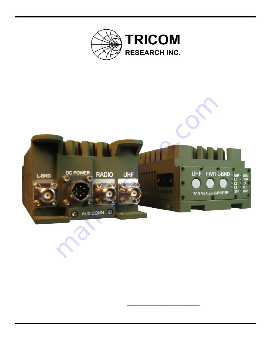
Страница 5: ...o provide transmit and receive gain for the following modes of operation SRW and ANW2 Wideband Networking Waveforms in the 225 450 MHz band UHF band SRW and ANW2 Wideband Networking Waveforms in the 1250 1390 MHz band L1 band SRW and ANW2 Wideband Networking Waveforms in the 1750 1850 MHz band L2 band L3 is for future use and consideration Part number 11000 00794 Figure 1 1 TCR U L 25 ...
Страница 6: ...erenced to 1 milliwatt 0 dBm 1 mW FM Frequency modulation Hz Hertz IW Integrated Waveform JITC Joint Interoperability Test Center DISA kHz Kilohertz LED Light emitting diode LNA Low Noise Amplifier LOS Line of sight MHz Megahertz mW Milliwatt PT Plain text PTT Push to Talk RCV Receive SATCOM Satellite Communications SF Single Frequency SRW Soldier Radio Waveform UHF Ultra high frequency VDC Volts ...
Страница 7: ...o the user via the front panel push buttons or with the remote interface and through Tx automatic mode detection UHF MODE BUTTON 225 450 MHz ANW2 SRW WB Wideband Networking Waveforms LNA ON LNA is always on in this system and mode L BND MODE BUTTON L1 ANW2 SRW WB Wideband Networking Waveforms LNA ON L2 ANW2 SRW WB Wideband Networking Waveforms LNA ON L3 Not used LNA is always on in this system and...
Страница 8: ...last operating mode If power is shut off using the PWR button and the DC supply is then disconnected and re connected the PA will likewise remain in the OFF state If PIN E on the DC input power connector is tied to Electrical GROUND auto start configuration and the DC power is disconnected and re connected the amplifier will automatically power ON into the last operational mode This feature is use...
Страница 9: ...cate a fault condition such as attempting to transmit at a frequency that is not valid in the selected mode or over temperature conditions 1 3 4 10 REMOTE OPERATION STATUS INDICATOR RMT The REMOTE LED will illuminate when the PA has received a REMOTE ON command from an external terminal and will stay on until the REMOTE OFF command has been received Note that the front panel UHF and L BND buttons ...
Страница 10: ...e band filtering to suppress interference from co located radios and amplifiers in UHF and L band modes Amplifier front panel indication of system status Automatic frequency mode detection and selection of proper mode UHF L1 L2 1 5 TCR U L 25 SYSTEM The TCR U L 25 is pictured in Figure 1 1 1 5 1 Amplifier Components The Amplifier consists of several printed circuit board assemblies a filtering and...
Страница 11: ...ations The operating parameters physical characteristics and environmental specifications are shown in the following tables Table 1 1 Nominal Performance Specifications TRANSMIT SECTION UHF OPERATION Frequency Range 225 450 MHz with Automatic Frequency Detection Band Selection Fully automatic RF Power Input 1 5 Watts 2W typical RF Power Output 25 W Avg L BAND OPERATION Frequency Range 1250 1390 MH...
Страница 12: ... back DC Off Routes Radio signal to UHF port Operating Temperature 30 to 60 C Cooling Natural Convection Dimensions 2 5 H x 3 5 W x 8 15 D Weight 5 2 lbs The information in section 1 6 is included for reference only and does not constitute a warranty of performance Table 1 2 Interconnect Characteristics Connection Signal Pin Connector Function DC IN DC power input PIN A PIN B PIN C PIN D PIN E PIN...
Страница 13: ... 2 Controls Indicators and Connectors The TCR U L 25 has three push button switches to control Power ON OFF and LED intensity PWR button UHF Modes of Operation UHF button L Band Modes of Operation L BND button There are also several status indicators on the amplifier s front panel as shown in Figure 2 1 The functions of these are specified in Tables 2 1 2 2 and 2 3 Figure 2 1 Amplifier Controls In...
Страница 14: ... RADIO input to the UHF connector output UHF MODE Push Button Switch Selects the UHF modes of operation refer to Table 2 1 L BND MODE Push Button Switch Selects the L Band modes of operation refer to Table 2 1 Table 2 3 I O Connectors CONNECTIONS TYPE FUNCTION UHF Antenna BNC Type RF connector Used to attach UHF Antenna RADIO BNC Type RF Connector Used to attach to Transceiver L BND Antenna BNC Ty...
Страница 15: ...U L 25 from power ON to power OFF UHF Bypass mode To switch the power amplifier back to the Power OFF Bypass mode press and hold the PWR button for more than 6 seconds the LEDs will dim as the PWR button is pressed and held down When in the Power OFF Bypass mode the RF is automatically routed to the UHF antenna port directly from the transceiver The Amplifier remembers the last state it was in whe...
Страница 16: ...at have a receive Low Noise Amplifier LNA Using the LNA with certain radios may cause intermittent squelch break on the radio 2 3 3 3 Remote Control Operation The TCR U L 25 can be controlled remotely via a USB or asynchronous RS 232 interface refer to section 3 for a functional description of these interfaces 2 3 3 4 Out of band operation Operating outside the frequency band for the selected mode...
Страница 17: ...t source FLT light flashes Constantly output power is reduced FLT light ON Radio connected to UHF port PA has exceeded its normal operating temperature limit PA has exceeded its high temperature limit and is in failsafe mode the equivalent of UHF Bypass Provide additional airflow or reduce transmission time The PA automatically reduces output power under high temperature conditions Operation will ...
Страница 18: ... existing mounting holes for the TCR MBA 25 and TCR MBA 50 WB power amplifiers refer to Figure 3 1 These holes accommodate 10 32 screws which screw into tapped 10 32 X 0 220 deep holes on the amplifier Ensure the proper length screw is used to prevent damage to the threaded holes on the amplifier The power amplifier can also be mounted by using two mounting tabs in the front and two mounting holes...
Страница 19: ...15 Figure 3 1 TCR U L 25 Outline Drawing 1 of 2 Mounting Tab Tricom Part 31002 01677 Use 100º 8 flat head screw ...
Страница 20: ...16 Figure 3 2 TCR U L 25 Outline Drawing 2 of 2 ...
Страница 21: ... pinout and location 3 5 RF Interconnections Attach an RF cable from the transceiver to the Radio Input Connector Attach RF cables antennas to the antenna connections located on the rear of the amplifier Figure 3 3 Amplifier DC input connector MS3112E10 6P Table 3 1 DC Input Power Connector Pinout Pin I O Connection Pin A I 12 32 VDC Pin B I Electrical GND Pin C I O Reserved Pin D I O Reserved Pin...
Страница 22: ...18 Figure 3 4 Military Vehicle DC Power Cable part number 77500 00412 included NC NC A B C D E 28V Electrical GND MS3116F10 6S Optional connection for Auto Power On green wire ...
Страница 23: ...he USB driver can be downloaded from http www ftdichip com drivers D2XX htm CAUTION The AUX CONN cover should be installed whenever the auxiliary port is not being used to maintain the environmental integrity of the PA and to prevent damage to the auxiliary connector contacts Figure 3 5 Auxiliary connector pinout mating connector part number 77500 00421 Table 3 2 Auxiliary Connector Pinout Pin I O...
Страница 24: ...igure 3 6 USB Remote Control Cable part number 77500 00391 optional Figure 3 7 RS 232 Remote Control Cable part number 77500 00390 optional 60 3 5 4 6 1 2 3 4 60 1 2 6 2 3 5 Ground TXD RXD 5 VDC D D Ground ...
Страница 25: ...own command message Table 3 3 Remote Control Command Set COMMAND FUNCTION remote on Turns on remote control function on the PA RMT light turns on mode UHF and L BND mode switches are disabled remote off Turns off remote control mode on the PA RMT light turns off Displays command list status Displays current status of the PA firmware versions mode power temperature amp serial number uhf wb hop lna ...
Страница 26: ...s USB serial adapter port both versions by going to the advanced comm port settings in the Device Manager s menu Comm port reassignment procedure 1 Ensure that the USB driver for the USB to serial adapter in the PA is installed on the computer The driver is loaded on the CD that ships with the PA or it can be downloaded from http www ftdichip com drivers D2XX htm NOTE The driver must be installed ...
Страница 27: ...ort 9 Click OK on the advanced settings window and verify that the reassigned comm port settings are 9600 bps 8 bits no parity 1 stop bit and no flow control 10 Click OK on the USB Serial Port Properties COM2 in this example window to return to the Device Manager main window Currently assigned comm port COM12 Desired comm port COM2 ...
Страница 28: ...C is communicating with the PA NOTE Any communications terminal software such as HyperTerminal can be used to communicate with the PA Windows 7 does not include the popular HyperTerminal software but there are several freeware communications terminal emulation utilities available for download on the internet such as PuTTY which can be downloaded from http www putty org Reassigned comm port COM2 ...