

6
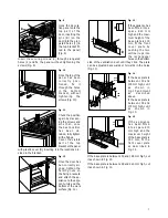
Door reversibility
Remove the two screws which fix the upper hinge to
the door.
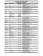
Carefully lean the appliance on its back and remove
the plastic insert (Fig. 4).
Fig. 4
Remove the two screws which fix the lower hinge to
the door.
Remove the four screws which fix the lower hinge to
the base of the appliance and remove the hinge itself;
be very careful to recover all the screws.
Remove the four screws that fix the upper hinge to the
appliance and remove the hinge itself.
Take the hinge removed from the upper part of the ap-
pliance on the opposite side (see Fig. 5), and, using
the screws removed from the lower part, fix it to the
base of the appliance itself.
Remove and refit the other hinge on the upper part of
the appliance on the opposite side.
Fig. 5
Fix the two front
s c re w s i n t o t h e
upper and lower
hinges (Fig. 5).
Finally, check the alignment of the door and make
sure it closes properly.
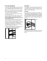
After having reversed the opening direction of the
door, discard the original plastic insert removed and fit
the insert supplied with the appliance on the opposite
side.
D447
D510
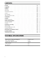
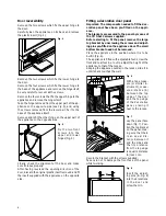
Fitting a decorative door panel
Important: The components needed to fit the dec-
orative panel have been pre-fitted on the appli-
ance.
The brackets are secured to the panel by means of
the 7 Ø 3.5x13 screws supplied.
Before starting to fit the panel, remove the large
top bracket by unscrewing the screws and adjust-
ing pins pre-fitted on the appliance door. The small
bottom bracket need not be removed.
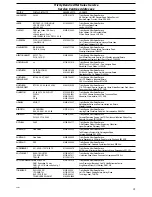
Place the appliance in the position where it is to be
built in (Fig. 6).
The appliance is fitted with adjustable feet; screw the
front and rear feet in or out to adjust the height of the
appliance to that of the recess.
Keeping the appliance central in the recess, slide it in
until its back touches the wall.
Fig. 6
With a tape meas-
ure (or similar in-
strument), meas-
u re d i s t a n c e ( A )
between the top
edge of the door
and the top edge
of the decorative
panel, placing it
next to the recess.
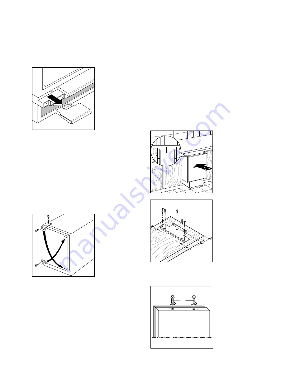
Fig. 7
Lay the panel face
down (Fig. 7). Posi-
tion the top bracket
on the panel, mak-
ing sure that there
i s a n e q u a l d i s -
tance between it
and the sides and
that its distance
from the top edge
is equal to distance
(A) less 1 cm.
Secure the bracket with the screws supplied.
Take care not to damage the front face of the panel
whilst working.
Fig. 8
Insert the adjust-
ing pins (B-Fig. 8)
into their locations
i n t h e d o o r a n d
screw them in.
D467
=
=
A
D468
A
-1cm
=
=
D532
B


