Trianco EuroStar Premier 100/125 Condensing Скачать руководство пользователя страница 18

6. FLUE SYSTEMS

To  evacuate the products of combustion safely and
thoroughly, the boiler must have an efficient flue system.
Under no  circumstances should the boiler be installed
using an existing flue system.       

All components used in the flue system should be suitable
for wet flues. The design and construction of the Trianco
balanced flue kits take these factors into account so the
following guidance notes are for conventional chimneys.
Reference should also be made to BS 5410 Part 1 if further
information is required on conventional chimneys.

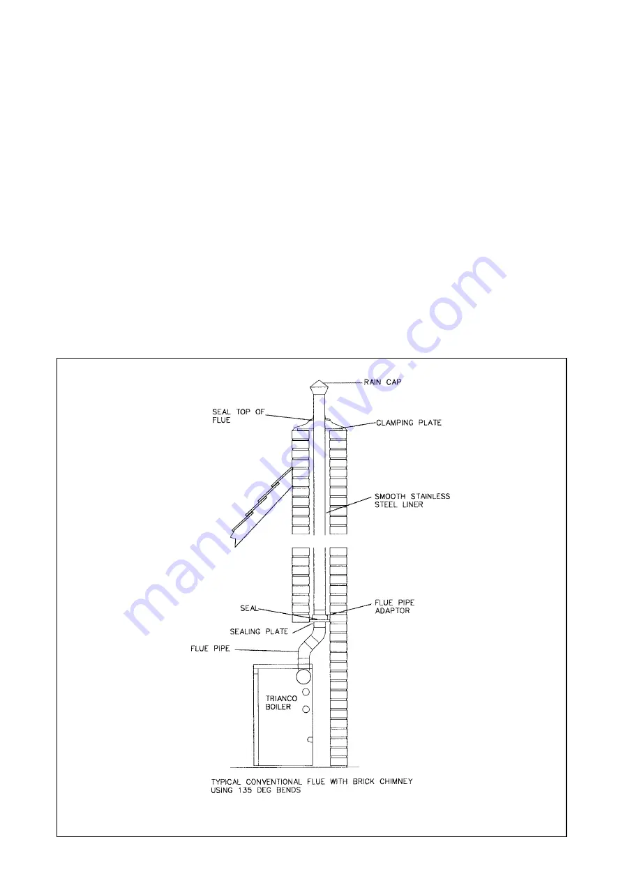
Conventional chimney (Fig. 14)

Trianco condensing boilers operate at high efficiencies
with low flue gas temperatures. The flue system used on
this boiler must be suitable for low flue gas temperatures
and condensation.

1  The chimney should rise as vertically as  possible and

terminate at a point not subject to down draughts or 
wind effects.           

2  The condensation produced in the flue system can be

allowed to run back in to the boiler. No separate drain
at the base of the flue system is required

3  Where an existing chimney is to be used it must be lined

with a stainless steel liner that is approved for use on
an oil fired condensing boiler. Note: Before fitting a flue
liner the chimney must be thoroughly cleaned free
from all traces of soot and scale. 

4  If a rigid flue is to be fitted externally a twin wall flue

must be used. The flue must be constructed with a
stainless steel inner skin (suitable for condensation),
insulation and incorporate seals and be weather proofed.

5  The internal flue diameter must be 100 mm (4 in) 

minimum.

6  The flue pipe between the boiler and the chimney must

be manufactured from 316 stainless steel or higher.
Aluminum or plastic must not be used on any part of the
flue system.

7  The in-built flue gas resistance of the Eurostar is such

that it allows the boiler to operate reliably over the wide
range of chimney draughts encountered from typical
domestic chimneys. Under normal draught conditions,
the flue should terminate with a standard cowl.

IMPORTANT
Ensure that all the joints on the flue system are sealed
and that no condense can escape.

15

FIG.14

Содержание EuroStar Premier 100/125 Condensing

Страница 1: ...d by householder USER INSTALLATION COMMISSIONING SERVICING INSTRUCTIONS OIL FIRED CENTRAL HEATING BOILERS FOR BALANCED OR CONVENTIONAL FLUE BED 92 42 EEC EMC 89 336 EEC Premier 50 90 Condensing Premie...

Страница 2: ...isposable gloves face masks and eye protection After handling wash hands and other exposed parts When disposing reduce dust with water spray ensure parts are securely wrapped GLUES SEALANTS PAINT Glue...

Страница 3: ...ilation 8 9 Extractor fan 9 Electrical supply 9 Condensate Drain Connection 10 5 OIL SUPPLY Oil storage tank Steel and Plastic 11 Oil supply line 11 Single pipe oil supply 12 13 Two pipe oil supply 12...

Страница 4: ...before contacting your Service Engineer 1 USER INSTRUCTIONS Please note to assist Trianco in improving customer service it is important that the guarantee registration card is returned HOW TO USE YOUR...

Страница 5: ...s ensure the oil storage tank is topped up regularly do not wait until the tank is nearly empty before refilling as sludge and water could be sucked into the oil pipe affecting the operation of the bu...

Страница 6: ...inted Service Agent must check all his work PRIOR to requesting Trianco to attend PLEASE NOTE Unauthorised invoices for attendance and repair work carried out on this appliance by any third party will...

Страница 7: ...BS 7593 requirements Always refer to the manufacturers instructions Failure to flush and add inhibitors to the system will invalidate the appliance warranty The appliance is designed to be fitted to...

Страница 8: ...IPE OR ELECTRIC CABLE ENTRY BOTH SIDES RETURN CONNECTION DIA 22MM EACH SIDE FLOW CONNECTION DIA 22MM EACH SIDE Heating Return Cleaning Hole Cleaning Hole Heating Return Heating Flow Condensate drain H...

Страница 9: ...36 kW 130 900 btu s 36 36 kW 60 000 btu s 17 58 kW 70 000 btu s 20 51 kW 80 000 btu s 23 44 kW 90 000 btu s 26 37 kW 100 000 btu s 29 3 kW 110 000 btu s 32 2 kW 120 000 btu s 35 2 kW 125 000 btu s 36...

Страница 10: ...FIG 5 WIRING DIAGRAM 7...

Страница 11: ...Local Water Undertakings By laws OFTEC Installation Requirements for Oil Fired Boilers and Oil Storage Tanks OFST 100 and OFST 200 Health and Safety at Work Act The installer should be aware of his re...

Страница 12: ...r ancillary controls See wiring diagram Fig 5 Warning High and Low Voltage In certain parts of the country where there is a known risk of high or low voltage fluctuations the oil burner shall be preve...

Страница 13: ...ternal waste drain If the boiler is to be fitted in a position where the external ground level is higher than the boiler and there are no internal drains a condensate pump can be fitted refer to pump...

Страница 14: ...t corrode and therefore never need painting c They are easier to handle because of their lower weight d They have a 10 year manufacturer s guarantee Plastic tanks should be fitted with similar compone...

Страница 15: ...released from the oil to affect combustion 2 The return pipe must end at the same level as the suction outlet to prevent loss of prime 3 The outlet from the tank should be approximately 75mm 3 in abo...

Страница 16: ...ID 10 21 31 41 52 62 73 83 PIPE 8mm ID 33 66 98 100 100 100 100 100 MAXIMUM OIL SUPPLY LINE LENGTH L MAXIMUM LENGTH METRES LIFT H METRES 0 5 1 0 1 5 2 0 2 5 3 0 3 5 4 0 PIPE 6mm ID 48 42 36 30 24 18 1...

Страница 17: ...14 FIG 13 DE AERATED OIL SUPPLY INSTALLATION REFER TO MANUFACTURERS INSTRUCTIONS FOR OIL DE AERATOR INSTALLATION DETAILS REMOTE OPERATED FIRE VALVE OIL FILTER...

Страница 18: ...the boiler No separate drain at the base of the flue system is required 3 Where an existing chimney is to be used it must be lined with a stainless steel liner that is approved for use on an oil fire...

Страница 19: ...t system which maintains the room sealed performance even when the casing door is removed for burner commissioning or adjustments The use of the balanced flue principle also enhances the overall therm...

Страница 20: ...5 Take flue socket plate off the top of boiler leaving the flue gasket in position 6 If the flue is to be fitted terminating to the left or right hand side of the boiler the corresponding section of s...

Страница 21: ...Fig 19 19 7 18...

Страница 22: ...SEALING PLATE 1 8 GASKET SUPPLIED WITH BOILER 9 FLUE PIPE O RING 1 10 JUBILEE CLIP 1 230mm ROUND KIT 2350 2351 Supplied with boiler Supplied with boiler IMPORTANT When installing the flue system it is...

Страница 23: ...nditions the system should be drained down Handing Over After completing the boiler installation the installer should make a thorough check of the system to ensure it is completely satisfactory and de...

Страница 24: ...tion making gas tight seal using washers and wing nuts previously removed 12 Check condensate trap to ensure the outlet is not obstructed 13 Refit the burner securing the air hose in position using th...

Страница 25: ...ell not seeing flame Clean photo cell and ensure it is fully plugged in Air trapped in pump Bleed off air through pressure gauge tapping Solenoid valve faulty Check coil for continuity and replace if...

Страница 26: ...OLENTLY Delayed ignition Check electrode setting and adjust to correct gap Check electrodes for damage Check HT leads for damage and positive connection BURNER REPEATEDLY Exhaust gas in combustion air...

Страница 27: ...50 4 223330 1 15 Boiler Bottom Baffle 2 223053 1 223336 1 16 Boiler Middle Baffle 2 223333 4 17 Condensing Unit Baffle 2 223076 2 223392 2 18 Boiler Flue Cover 223019 1 223378 1 19 Condensing Unit Flu...

Страница 28: ...Copyright in this brochure and the drawings or illustrations contained in it is vested in Trianco Limited and neither the brochure or any part thereof may be reproduced without prior written consent T...

Отзывы: