Drive Configuration
Controller Tuning
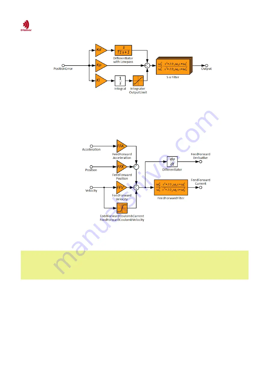
Figure 50 shows the block diagram for current feed forward. Beside the feed forward of position, veloc-
ity and acceleration also coulomb friction can be compensated. The
FeedForwardFilter
can be used to
fine tune the feed-forward transfer function.
5.4.4 Tuning of a Single-Loop Position Controller
Important
Important
The current controller (inner loop) has to be setup before the position controller (outer
loop). This is because the parametrization of the current controller influences the char-
acteristics of the position controller. The current controller in contrast is independent of
the parametrization of the position controller.
This section describes the tuning of a single loop position controller
. With single-loop setup, only one
position feedback is used for control.
If the loaded
Bode
measurement contains only one encoder signal, this signal is automatically used
for the tuning. The radio buttons
Position 1
are grayed out and
Single Loop
is set permanently.
If the loaded
Bode
measurement contains signals from two encoders,
Single Loop
is set by default
and should only be changed for dual-loop control . The signal used for the tuning can be selected as
follows:
With
Position 0
latched, the signal from Encoder[0] is used.
10 For other typologies see application note [10] for dual loop axes and [12] for gantry axes.
ServoDrive-SetupGuide_EP018
2022-08-25
59
/
83
Figure 49: Block-diagram of the PIDT1 position controller.
Figure 50: Block-diagram of the current feed forward.


