How to use TAM System Explorer
Topology Tree
Note
Note
The register
Axes[].Informaton.AxisName
is used by the axis monitor, the scope and the
modules to display the axis identification.
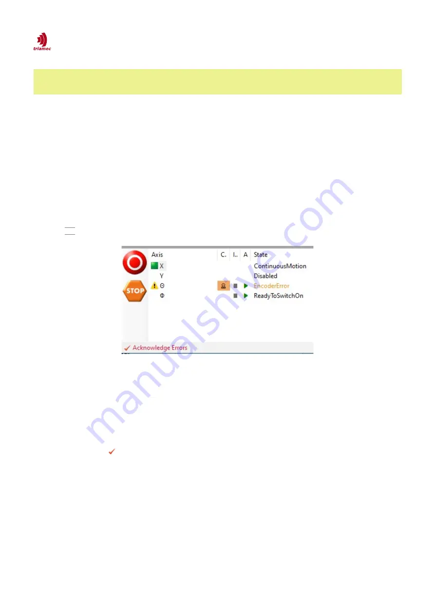
3.2 Axis Monitor
Below the
Topology Tree
the axes are listed in the axis monitor as a flat list.
The axes are identified by the register
Axes[].Information.AxisName
. Initially the station name is added
in front of
AxisName
, but will be removed when the axis name is changed the first time.
The axis name can be changed by selecting the axis name in the axis monitor and clicking it again or by
pressing F2 . The modified axis name is also stored in the register
Axes[].Information.AxisName
.
The axes are highlighted according to their state:
Enabled:
Enabled axes are marked with a green square.
Error:
If an axis has a problem, the axis is marked with an error icon. The error type is shown in the
State
column, highlighted in red. Resolved errors don't simply disappear. They need to be acknowl-
edged using the
Acknowledge Errors
button. If no errors are pending for acknowledgment, this
button is grayed out.
Warning:
Orange state color indicates a warning.
Warnings as well as errors which can't yet be acknowledged need some interaction, for example provid-
ing the required DC bus voltage in case of a
DcBusVoltageOutOfRange
warning.
The
Control system overridden
column shows a slowly blinking icon on orange background as long
👷
as an axis module is attached (see chapter 4.1).
The
Asy VM
and
Iso VM
columns reflect the states of the asynchronous and isochronous
Tama
virtual
machines (see chapter 3.7). Different characters are shown depending on the state.
ServoDrive-SetupGuide_EP018
2022-08-25
11
/
83
Figure 4: The axis monitor shows the state for each axis and
allows to acknowledge pending errors. Additionally, the
emergency buttons are provided.


