


28 August 2004
HEBC+ Manual
Tri-M Engineering
Tel:
800.665.5600, 604.945.9565
1407 Kebet Way, Unit 100
Fax:
604.945.9566
Port Coquitlam, BC, V3C 6L3
E-mail:
Canada
Web
site:
www.tri-m.com
5
CHAPTER 2 - CONFIGURATION AND INSTALLATION
2.1 Introduction
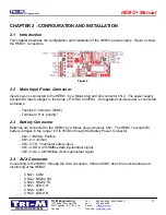
This chapter describes the configuration and installation of the HEBC+ power supply.
Figure 2
shows
the HEBC+ connectors.
Figure 2
2.2 Main Input Power Connector
Input power is connected to the HEBC+ by a Molex plug and pin connector CN2. The power supply
accepts DC input voltages in the range of 10VDC to 40VDC. Unregulated vehicle power is connected
as follows:
- Terminal 1:Common (0VDC)
- Terminal 2: Hot ”polarity”
2.3 Battery
Connector
Batteries are connected to the HEBC+ by a Molex plug connector, CN1. The HEBC+ accepts DC
battery voltages in the range 10V to 35VDC through the Battery Power Connector.
-
CN1-1: Battery Positive
-
CN1-2: Common
-
CN1-3: TH, Thermistor safety input
-
CN1-4: SDA, I2C/SMBus data input/output signal
-
CN1-5: SCL, I2C/SMBus clock input/output signal
2.4 AUX
Connector
Connecting to the HEBC+ through the AUX connector, CN4 and CN5, does the remote setup and
monitoring of the HEBC+.
-
CN4-1: COM
-
CN4-2: RS232 RX
-
CN4-3: RS232 TX
-
CN5-1: LED-CH
-
CN5-2: COM
-
CN5-3: LED-HB