background image

VJS/AG/36

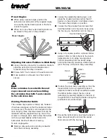
90°

60°

120°

45°

135°

30°

150°

(-30º)

(-45º)

(-60º)

Preset Angles

Adjusting Extrusion Position to Main Body

I

Loosen the alloy connector to extrusion knobs to
allow the extrusion to be slid backwards or
forwards along the alloy connector. 

I

Ensure both T-nuts remain in the extrusion slot.

I

Once position is achieved, lock the knobs to
secure.

Preset Angles

I

When using a preset angle, position the
extrusion and protractor at the required angle
and use the knurled locking knob in the hole
to lock the guide.

I

When not in use the knurled locking knob can
be stored in the park on the protractor

If the extrusion is used with the end
caps removed ensure when sliding
the extrusion that both T-nuts remain
in the extrusion slot. 

Zeroing Protractor Guide

The variable angle guide is factory set, however
it has been designed so that the angle protractor
can be zeroed. The bottom rail is secured to the
main body by three machine screws that can be
loosened with the supplied hex key. Two of the
screws run through slots, which allow the bottom
rail to be pivoted slightly, either forward or
backwards which will allow for zeroing.

To zero angle guide:-

I

Remove alloy extrusion and alloy connector 
from the main body assembly. 

I

Loosen the adjustable locking lever, and 
place the knurled locking knob at the 90°
position in the protractor, and tighten down. 
This locks the protractor in position.

I

Loosen the three socket head screws that 
hold the bottom rail to the main body using 
the hex key, so the bottom rail can move.

I

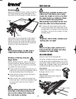
Using a try square position a planed timber 
batten (12mm to 18mm thick) to the bench 
perpendicular to an edge, leaving about 
100mm projecting from the bench edge, 
and clamp securely (ensuring clamps will not 
get in the way of the main body assembly).

3

2

1

0

90

30

30

5

5

Knurled locking knob

Batten

Square

Clamp

Bench

Clamp

90°

I

Position the main body assembly so that the
loose bottom rail is up against the bench
edge and slide main body assembly towards
the timber batten. Adjust the main body
assembly (by pivoting slightly) so the end of
the protractor is touching the batten along the
protractor ends entire length. 

0

90

30

30

5

5

3

2

1

0

90

30

30

5

5

I

Ensure the bottom rail is touching the bench
edge along its length and lock the socket
head screws with the hex key. 

-7-

MANU/VJS/AG/36 v1.0  3/2/10  12:57  Page 7

Содержание VJS/AG/36

Страница 1: ...VJS AG 36 VARIJIG VARIABLE ANGLE GUIDE 36 915mm...

Страница 2: ...ARE PARTS Spare Parts List ____________________11 Spare Parts Diagram ________________12 TECHNICAL DATA Extension thickness 15 8mm Extension width 54 0mm Working length at 90 Router 915mm Circular Saw...

Страница 3: ...hands on the power tool and attachment Keep both hands away from cutting area Always wait for the spindle and cutter to stop rotating before making any adjustments 10 Always keep guards in place and...

Страница 4: ...p a cut in one pass can stall the router 15 In case of excessive vibrations whilst using the router stop immediately and have the eccentricity of the router router cutter and clamping system checked b...

Страница 5: ...VJS AG 36 4 ITEMS ENCLOSED ITEMS REQUIRED I Plunge router or jigsaw circular saw I Clamps x 3 I Hand tools x1 x1 x2 x2 x1 x1 x1 x1 x1 x1 x1 x1 x2 x2 x2 x2 GUARANTEE VJS AG 36 fitted to protractor x2...

Страница 6: ...ractor knobs female H Alloy connector to protractor plate fixing screws I Plastic washer J T nut K Knurled locking knob L Adjustable locking lever female M Adjustable locking lever plastic washer N Ma...

Страница 7: ...ad sits in the channel and then the metal washers Loosely tighten female knobs onto the screws I Fit the alloy connector to the alloy extrusion by locating the two holes of the alloy connector with th...

Страница 8: ...be pivoted slightly either forward or backwards which will allow for zeroing To zero angle guide I Remove alloy extrusion and alloy connector from the main body assembly I Loosen the adjustable locki...

Страница 9: ...the same saw or same router and router cutter diameter combination are being used two spacers can be made to the same width as the offset to aid setting up in future X Offset distance required from ed...

Страница 10: ...saw plate to raise the motor higher if necessary When using a portable circular saw which has a left sided motor body ensure the depth of cut is set so that the motor body is a minimum 35mm 1 3 8 abo...

Страница 11: ...with a soft cloth Lubrication I Your accessory requires no additional lubrication Storage I Store accessory safely on wall hooks ENVIRONMENTAL PROTECTION Recycle raw materials instead of disposing as...

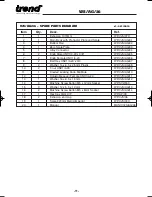
Страница 12: ...Bolt Hex UNC1 4 20 x 3 4 WP VJS AG 07 9 2 Washer 14 x 6 5 x 2 5mm Plastic WP VJS AG 08 10 2 T nut UNC1 4 20 WP VJS AG 09 11 1 Knurled Locking Knob M6 Male WP VJS AG 10 12 1 Adjustable Lever Female UN...

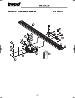
Страница 13: ...VJS AG 36 12 20 14 15 17 11 12 9 16 4 7 3 2 8 1 6 9 10 18 19 5 13 13 13 VJS AG 36 SPARE PARTS DIAGRAM V1 0 01 2010...

Страница 14: ...us improvement means that specifications may change without notice Trend Machinery and Cutting Tools cannot be held liable for any material rendered unusable or any form of consequential loss E OE REC...

Отзывы: