background image

28 • TRX-4

ADJUSTING YOUR MODEL

# Spur Gear Teeth

x 15.8 =  Final Gear Ratio

# Pinion Gear Teeth


CAUTION: 

The stock gearing (11-T pinion  

                     and 45-T spur gear) is suitable for general  
                     use in most terrain with NiMH or 2s/3s LiPo 
batteries. If you decide to modify the gear ratio, use  
caution to avoid damage to your vehicle’s electronics.   

Use the following formula to calculate the overall ratio for 
combinations not listed on the gear chart:

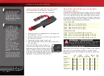
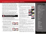
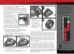
Adjusting Gear Mesh

Incorrect gear mesh is the most 
common cause of stripped spur 
gears. Your model includes a fixed 
gear positioning system to simplify 
the process and ensure proper gear 
mesh settings. Access the gears by 
removing the three 3x8mm button-
head screws from the gear cover; 
remove the gear cover. Remove the 
motor/motor plate assembly from 
the chassis.

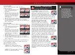
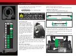
To set the gear mesh, use the chart 
to the left to identify the screw 
positions on the motor plate (A - H) 
that correspond with the chosen 
motor pinion (9-T - 22-T) and spur gear size (39-T or 45-T). Remove 
the two screws from the motor/motor plate and reinstall in the 
corresponding positions; reinstall the motor/motor plate assembly 
in the chassis.

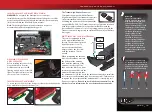
Motor Removal/Installation

To access the motor, remove the gear cover by removing the three 
3x8mm button-head cap screws. Remove the motor/motor plate 
assembly from the chassis; then, remove the two screws holding 
the motor to the motor plate. Installation of the motor is the 
reverse of removal.

SERVO STEERING SYSTEM

TRX-4 uses a single metal gear servo for powerful, responsive steering.  

Adjusting the Steering System

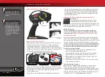
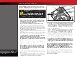
1.  Remove the servo horn and steering links from the servo. 
2.  Adjust the drag link to 133.2mm; adjust the steering link to 77.3mm.

3.  Switch on the power to the receiver and the transmitter.
4.  Adjust the steering trim on the transmitter to the neutral “0” position.
5.  Connect one end of a steering link to the steering servo arm and the 

other end to the servo horn.

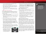
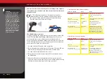
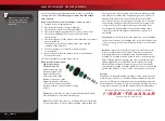
6.  Position the servo horn perpendicular to the centerline of the vehicle 

as shown below.

Spur Gear

Pinion Gear

39

45

9

-

A

10

-

B

11

-

C

12

-

D

13

-

E

14

-

F

15

A

G

16

B

H

17

C

-

18

D

-

19

E

-

20

F

-

21

G

-

22

H

-

Stock factory gearing

Does not fit

Screw Positions

133.2mm

Drag Link

77.3mm

Steering Link

Front of 

Truck

Содержание 82034-4

Страница 1: ...MODEL 82034 4 owner s manual EQUIPPED WITH ...

Страница 2: ...r to the next page to find out how to contact us and what your support options are Quick Start This manual is designed with a Quick Start path that outlines the necessary procedures to get your model up and running in the shortest time possible If you are an experienced R C enthusiast you will find it helpful and fast Be sure and read through the rest of the manual to learn about important safety ...

Страница 3: ...arnings Helpful Hints Cross References Throughout this manual you ll notice warnings and helpful hints identified by the icons below Be sure to read them An important warning about personal safety or avoiding damage to your model and related components Special advice from Traxxas to make things easier and more fun Refers you to a page with a related topic SUPPORT If you have any questions about yo...

Страница 4: ...c device capable of delivering high current Please closely follow these precautions to prevent damage to the speed control or other components Disconnect the Battery Always disconnect the battery from the speed control when not in use Insulate the Wires Always insulate exposed wiring with heat shrink tubing to prevent short circuits 6 7 NiMH cells or 2 3 LiPo cells 2s 3s The XL 5 HV can accept a m...

Страница 5: ... parallel Charging packs in series or parallel may result in improper charger cell recognition and an improper charging rate that may lead to overcharging cell imbalance cell damage and fire FIRE HAZARD WARNING CAUTION DANGER ALWAYS inspect your LiPo batteries carefully before charging Look for any loose leads or connectors damaged wire insulation damaged cell packaging impact damage fluid leaks s...

Страница 6: ...skin contact occurs flush with water If a battery gets hot to the touch during the charging process temperature greater than 110 F 43 C immediately disconnect the battery from the charger and discontinue charging Allow the battery pack to cool off between runs before charging ALWAYS unplug the charger and disconnect the battery when not in use ALWAYS unplug the battery from the electronic speed co...

Страница 7: ... Your model comes with a set of specialty metric tools You ll need to purchase other items available from your hobby dealer to operate and maintain your model Supplied Tools and Equipment Required Equipment not included Battery and charger style are subject to change and may vary from images 4 way wrench 2 0mm T wrench 1 5mm L wrench 2 5mm L wrench 4 AA alkaline batteries Battery charger Traxxas i...

Страница 8: ...er Box Chassis Rail Front Bumper Electronic Speed Control Battery Hold Down Transmission Antenna Mount Front Body Mount Motor Traxxas High Current Connector Rear Body Mount Steering Servo Rear Bumper Rock Slider Battery Compartment Chassis Top View LED Lighting Module ...

Страница 9: ...e Rear Axle Front Axle Rear Portal Housing Front Portal Housing Floor Pan Caster Block Rear Lower Link Front Lower Link Rear Driveshaft Front Driveshaft Rear Upper Link Front Upper Link Differential Cover Chassis Bottom View Chassis Rail ...

Страница 10: ... pack See page 14 8 Detail your model See page 11 Your model requires a battery pack and a compatible battery charger not included Never use a NiMH or NiCad charger to charge LiPo batteries Apply other decals if desired 4 Install battery packs in the model See page 15 9 Drive your model See page 22 Your model requires a fully charged battery pack not included Driving tips and adjustments for your ...

Страница 11: ...ecise digital proportional throttle control Electronic speed controls use power more efficiently than mechanical speed controls so that the batteries run longer An electronic speed control also has circuitry that prevents loss of steering and throttle control as the batteries lose their charge Frequency band The radio frequency used by the transmitter to send signals to your model This model opera...

Страница 12: ...he hose voltage corresponds to the pressure that is forcing the water through the hose 550 and 540 These numbers refer to the size of the motor 550 motors have armatures that are 30 longer than 540 motors IMPORTANT RADIO SYSTEM PRECAUTIONS Do not kink the receiver antenna wire Kinks in the antenna wire will reduce range DO NOT CUT any part of the receiver antenna wire Cutting the antenna will redu...

Страница 13: ...eel Power Switch Battery Compartment Set Button Red Green Status LED MODEL WIRING DIAGRAM KA186 7 R 00 KA186 7 R 00 CH3 Channel 3 CH2 Speed Control CH1 Steering Servo CH1 Channel 1 not used Antenna Receiver Motor Titan 550 Traxxas High Current Connector Male to Battery XL 5 HV Electronic Speed Control Channel 2 Steering Servo Channel 1 Steering Trim Steering Trim TRX 4 13 TRAXXAS TQ 2 4GHz RADIO S...

Страница 14: ...ries Caution Discontinue running your model at the first sign of weak batteries flashing red light to avoid losing control SELECTING BATTERIES AND A CHARGER FOR YOUR MODEL Your model does not include a battery or charger The speed control in the model is compatible with both LiPo and NiMH batteries One NiMH or 2s 3s LiPo battery equipped with a Traxxas High Current Connector is required Traxxas Po...

Страница 15: ...een set up and installed from the factory The antenna is secured by a 3x4mm set screw To remove the antenna tube simply remove the set screw with the included 1 5mm wrench When reinstalling the antenna first slide the antenna wire into the bottom of the antenna tube until the white tip of the antenna is at the top of the tube under the black cap Next insert the antenna tube into the mount while ma...

Страница 16: ...rvo For example if you turn the steering wheel to the right and the model turns left Channel 1 would need to be reversed to correct the servo direction Use the following procedures to reverse the steering and throttle channels if necessary Servo reversing should only be required if you accidentally reset the direction of a channel Do not reverse the steering or throttle channels unless necessary S...

Страница 17: ...e trigger is at neutral WARNING Do not apply full throttle in forward or reverse while the model is elevated 8 Once adjustments are made turn off the receiver on your model followed by the hand held transmitter Range Testing the Radio System Before each running session with your model you should range test your radio system to ensure that it operates properly 1 Turn on the radio system and check i...

Страница 18: ...duce radio range TRANSMITTER LED CODES LED Color Pattern Name Notes Solid green Normal Driving Mode See page 16 for information on how to use the transmitter controls Slow red 0 5 sec on 0 5 sec off Binding See this page for more information on binding Flashing medium red 0 25 sec on 0 25 sec off Low Battery Alarm Put new batteries in the transmitter See page 14 for more information Flashing fast ...

Страница 19: ...ection is now ACTIVATED For NiMH battery users follow these steps to disable Low Voltage Detection NiMH setting 1 Make sure the LED on the XL 5 HV is on and GREEN 2 Press and hold the EZ Set button the LED will turn off After ten seconds the motor will beep three times and the LED will shine RED Release the button 3 Low Voltage Detection is now DISABLED XL 5 HV Setup Programming Calibrating your E...

Страница 20: ...de 100 forward brakes and reverse added brake drag when the throttle trigger is at neutral To activate full power without the additional brake drag Sport Mode disable reverse Race Mode allow 50 power patented Training Mode or set immediate reverse Crawl Mode follow these steps The speed control should be connected to the receiver and the transmitter adjusted as described previously The profiles ar...

Страница 21: ...ht Low Voltage Detection is DISABLED NiMH setting Fast Blinking Red Overtemp The XL 5 HV is equipped with thermal shutdown protection to guard against overheating caused by excessive current flow If the operating temperature exceeds safe limits the XL 5 HV will automatically shut down Let the XL 5 HV cool before continuing The ESC can get too hot in situations such as climbing and crawling in high...

Страница 22: ...h of the track This is normal and will not cause damage to your truck Check for any obstructions and or reposition the truck before continuing Observe the rollover height when driving over tall obstacles Do not attempt to climb obstacles that are taller than the rollover height of the Traxx Be careful when reversing The trailing wheel has a much lower rollover height than the leading wheels some o...

Страница 23: ...ement weather where lightning may be present Do not allow your model to come in contact with saltwater ocean water brackish water between fresh water and ocean water or other contaminated water Saltwater is highly conductive and highly corrosive Use caution if you plan to run your model on or near a beach Even casual water contact can reduce the life of your motor Special care must be taken to mod...

Страница 24: ...nd Installing Radio Gear The unique design of the receiver box allows the removal and installation of the receiver without losing the ability to maintain a watertight seal in the box The patent pending wire clamp feature gives you the ability to also install aftermarket radio systems and maintain the watertight features of the receiver box Removing the Receiver 1 To remove the cover remove the thr...

Страница 25: ...ould be increased with higher viscosity oil if the model is bottoming easily over jumps or when stiffer springs are installed Damping should be decreased with thinner viscosity oil if the model is hopping over small bumps and feels unstable or when softer springs are installed The viscosity of shock oil is affected by extremes in operating temperature an oil of certain viscosity will become less v...

Страница 26: ... slipper shaft To tighten or loosen the slipper nut insert the 2 0mm hex wrench into the hole in the end of the slipper shaft This locks the shaft for adjustments To restore factory settings use the included 4 way wrench to turn the adjustment nut until all four spring washers are flat then tighten the nut an additional 1 16 turn or until the slipper clutch does not allow the spur gear to slip dur...

Страница 27: ...e TRX 4 s Titan 550 Motor has been carefully matched to the needs of the TRX 4 The Titan 550 is made to run efficiently at high voltage to provide more torque and longer run times We do not recommend converting the TRX 4 to a typical low voltage setup using traditional 540 size motors While these components will physically fit into the TRX 4 the system will not run as efficiently losing power in t...

Страница 28: ...ws from the motor motor plate and reinstall in the corresponding positions reinstall the motor motor plate assembly in the chassis Motor Removal Installation To access the motor remove the gear cover by removing the three 3x8mm button head cap screws Remove the motor motor plate assembly from the chassis then remove the two screws holding the motor to the motor plate Installation of the motor is t...

Страница 29: ...kage mounting hole to the servo mounting hole FITTING AFTERMARKET BODIES Rear Shock Tower The rear shock tower can be installed in two different locations and in two orientations each This is to allow precise angle adjustment of the rear shocks The shock cap hollow balls can also be replaced with offset versions part 5355 sold separately to further fine tune the shock angle ...

Страница 30: ...motor oil Shocks Keep the oil level in the shocks full Use only 100 pure silicone shock oil to prolong the life of the seals If you are experiencing leakage around the top of the shock inspect the o ring in the top cap for signs of damage or distortion from overtightening If the bottom of the shock is leaking then it is time for a rebuild The Traxxas rebuild kit for two shocks is part 8262 Suspens...

Страница 31: ...TRX 4 31 ...
Страница 32: ...MODEL 82034 4 owner s manual 6250 Traxxas Way McKinney Texas 75070 1 888 TRAXXAS 190614 82034 4 OM EN R00 EQUIPPED WITH ...

Отзывы: