


TRAXXAS RALLY • 23
ADVANCED TUNING ADJUSTMENTS
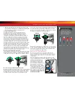
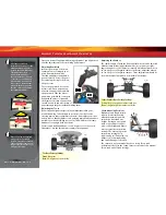
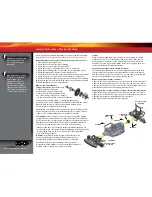
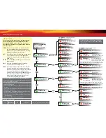
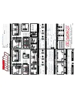
CAMBER GAIN
Your model has provisions for adjusting the camber gain geometry of
the front and rear suspension. “Camber gain” refers to an increase in
camber angle as the suspension is compressed. The camber gain of the
vehicle can be changed by moving the camber link attachment to a
different horizontal mounting position. Adjusting the camber gain will
alter the tire contact patch as the suspension is compressed. Making
the camber link shorter will increase the camber gain. This makes
the vehicle more stable over bumps, but reduces traction on smooth
surfaces. Lengthening the camber links has the opposite effect.
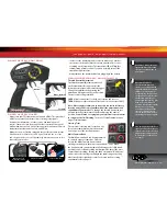
• Front Camber Gain
To increase the camber gain on the front
suspension, move the inner camber link
ends out to Position 3. Position 4 is the
stock setting.
• Rear Camber Gain
To increase the camber gain on the rear
suspension, move the inner camber link
ends out to a different attachment hole
(Position 1, 2 or 4 in the image. Position 5
is the stock setting).
Once you make adjustments to the camber
gain, you may need to re-adjust the static camber to suit
your tuning needs.
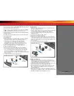
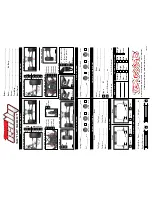
ROLL CENTER
Your model has provisions for adjusting the roll center geometry of the
front and rear suspension. Roll center refers to the virtual axis around
which the chassis will roll when subjected to cornering forces. The roll
center of the vehicle can be raised by mounting the inner ends of the
camber links in a lower position. Raising the roll center will effectively
increase the roll stiffness of the vehicle (similar to installing swaybars).
Adding roll resistance to one end of the vehicle will tend to add traction
to the opposite end. For example, increasing roll resistance in the
rear will provide more traction for the front wheels and potentially
more steering. Raising the roll center on the front and rear equally will
increase overall roll resistance without changing the handling balance.
The default factory locations are designed to make your model easier
and more forgiving to drive and less likely to traction roll in turns.
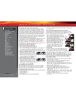
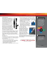
• Front Roll Center
To lower the roll center on
the front suspension, move
the inner camber link ends
up to a different attachment
hole (Position 1 or 2.
Position 4 is the stock setting). To lower the roll center further, move the
outer camber link ends to the lower position on the C-hub.
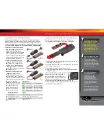
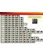
Bump steer correction
- “Bump steer” refers to
unwanted steering inputs caused by suspension
movement. The model’s suspension geometry is
designed to minimize bump-steer. If you are using
the upper hole on the C-hub (image A) and either
of the two lower holes on the shock
tower (positions 3 or 4 in “Front”
image), the tie rod ball should be
oriented with the large flat end on
top (stock position - image B). When
using any other combination of
camber link attachment points, the tie rod
ball should be oriented with the large flat
end on the bottom (C).
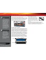
• Rear Roll Center
To lower the roll center
on the rear suspension, relocate the inner
camber links to one of the three holes
(position 1, 2 or 3 in image) in the upper row of the rear camber link
attachment, located near the base of the rear shock tower.
Once you make adjustments to the roll center, you may need to
re-adjust the static camber to suit your tuning needs.
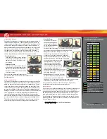
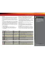
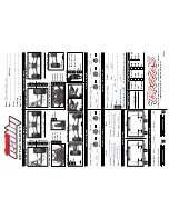
GEARING
One of the more significant advantages to your model’s transmission
is the extremely wide range of available gear ratios. Changing the
gearing allows you to fine tune the speed of your model and control
the temperatures of the battery pack and motor. Use a lower gear
ratio (numerically larger) to reduce current draw and temperatures.
Use a higher gear (numerically lower) to increase top speed. Use the
following formula to calculate the overall ratio for combinations not
listed on the gear chart:
Front
Front
C-hub
Rear
Rear
B
C
# Spur Gear Teeth
x 2.85 = Final Gear Ratio
# Pinion Gear Teeth
A
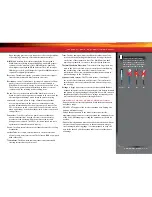
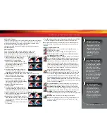
Gearing Compatibility Chart:
The chart below shows recommended
gear combination ranges for your model.
Spur Gear
Pinion Gear
50
52
54
9
-
16.44
17.08
10
-
14.80
15.37
11
12.94
13.45
13.97
12
11.86
12.33
12.81
13
10.95
11.38
11.82
14
10.16
10.57
10.98
15
9.49
9.87
10.25
16
8.89
9.25
9.61
17
8.37
8.71
9.04
18
7.91
8.22
8.54
19
7.49
7.79
8.09
20
7.12
7.40
7.68
21
6.78
7.05
7.32
22
6.47
6.73
-
23
6.19
6.43
-
24
5.93
-
-
25
5.69
-
-
26
-
-
-
Thick black border indicates stock settings.
Out of Box Setup, recommended for most
running, 6 or 7-cell NiMH, 2S LiPo
Recommended gear range for 6 or 7-cell
NiMH
Included optional gearing, for high-speed
running only
Fits, for high-speed runs only, not
recommended for use with NiMH batteries
High-current LiPo batteries required.


