Traxxas 020334940711 Скачать руководство пользователя страница 30

30 • DRAG SLASH

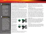
Your Traxxas transmitter has a programmable Multi-Function knob 
that can be set to control various advanced transmitter functions (set to 
Traxxas Stability Management (TSM) by default, see page 17). Accessing 
the programming menu is done by using the menu and set buttons on 
the transmitter and observing signals from the LED. An explanation of 
the menu structure follows on page 31. Experiment with the settings and 
features to see if they can improve your driving experience.  

Steering Sensitivity (Exponential)

The Multi-Function knob on the TQi transmitter can be set to control 
Steering Sensitivity (also known as exponential). The standard setting 
for Steering Sensitivity is “normal (zero exponential)”, with the dial full 
left in its range of travel. This setting provides linear servo response: the 
steering servo’s movement will correspond exactly with the input from 
the transmitter’s steering wheel. Turning the knob clockwise from the 
left will result in “negative exponential” and decrease steering sensitivity 
by making the servo less responsive near neutral, with increasing 
sensitivity as the servo nears the limits of its travel range. The farther 
you turn the knob, the more pronounced the change in steering servo 
movement will be. The term “exponential” comes from this effect; 
the servo’s travel changes exponentially relative to the input from the 
steering wheel. The exponential effect is indicated as a percentage—the 
greater the percentage, the greater the effect. The illustrations below 
show how this works. 

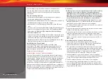
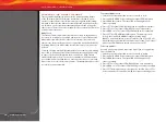
Normal Steering Sensitivity (0% 
exponential): 

In this illustration, 

the steering servo’s travel (and 
with it, the steering motion 
of the model’s front wheels) 
corresponds precisely with the 
steering wheel. The ranges are 
exaggerated for illustrative 
purposes.

Decreased Steering Sensitivity 
(Negative Exponential):

 By 

turning the Multi-Function 
knob clockwise, the steering 
sensitivity of the model will 
be decreased. Note that a 
relatively large amount of 
steering wheel travel results 
in a smaller amount of servo 
travel. The farther you turn the 
knob, the more pronounced 
the effect becomes. Decreased 
steering sensitivity may be helpful when driving on low-traction surfaces, when 
driving at high speed, or on tracks that favor sweeping turns where gentle steering 
inputs are required. The ranges are exaggerated for illustrative purposes.

Throttle Sensitivity (Throttle Exponential)

The Multi-Function knob can be set to control Throttle Sensitivity. 
Throttle Sensitivity works the same way as Steering Sensitivity, but 
applies the effect to the throttle channel. Only forward throttle is 
affected; brake/reverse travel remains linear regardless of the Throttle 
Sensitivity setting. 

Steering Percentage (Dual-Rate)

The Multi-Function knob can be set to control the amount (percentage) 
of servo travel applied to steering. Turning the Multi-Function knob 
fully clockwise will deliver maximum steering throw; turning the 
knob counterclockwise reduces steering throw (note: turning the dial 
counterclockwise to its stop will eliminate all servo travel). Be aware 
that the steering End Point settings define the servo’s maximum 
steering throw. If you set Steering Percentage to 100% (by turning the 
Multi-Function knob fully clockwise), the servo will travel all the way to 
its selected end point, but not past it. Many racers set Dual-Rate so they 
have only as much steering throw as they need for the track’s tightest 
turn, thus making the model easier to drive throughout the rest of the 
course. Reducing steering throw can also be useful in making a model 
easier to control on high-traction surfaces, and limiting steering output 
for oval racing where large amounts of steering travel are not required. 

Braking Percentage

The Multi-Function knob may also be set to control the amount of brake 
travel applied by the servo in a nitro-powered model. Electric models do 
not have a servo-operated brake, but the Braking Percentage function 
still operates the same way in electric models. Turning the Multi-Function 
knob full clockwise will deliver maximum brake throw; turning the 
knob counterclockwise reduces brake throw (

Note

: Turning the dial 

counterclockwise to its stop will eliminate all brake action).

Throttle Trim

Setting the Multi-Function knob to serve as throttle trim will allow you 
to adjust the throttle’s neutral position to prevent unwanted brake drag 
or throttle application when the transmitter trigger is at neutral. 

Note

Your transmitter is equipped with a Throttle Trim Seek mode to prevent 
accidental runaways. See the sidebar for more information.

Starting Over:


Restoring Factory Defaults

When programming your 
TQi transmitter, you may feel 
the need to start over with 
a clean slate. Follow these 
simple steps to restore the 
factory settings:
1. Turn the transmitter off.
2. Hold both MENU and SET.
3. Turn the transmitter on.
4. Release MENU and SET. 

The transmitter LED will 
blink red.

5. Press SET to clear settings. 

The LED will turn solid 
green and the transmitter 
is restored to default.

Throttle Trim Seek Mode

When the Multi-Function knob is 
set to throttle trim, the transmitter 
remembers the throttle trim 
setting. If the throttle trim knob is 
moved from the original setting 
while the transmitter is off, or while 
the transmitter was used to control 
another model, the transmitter 
ignores the actual position of 
the trim knob. This prevents the 
model from accidentally running 
away. The LED on the face of the 
transmitter will rapidly blink green 
and the throttle trim knob (Multi-
Function knob) will not adjust the 
trim until it is moved back to its 
original position saved in memory. 
To restore throttle trim control, 
simply turn the Multi-Function 
knob either direction until the LED 
stops blinking. 

TQ

i

 ADVANCED TUNING GUIDE

Turning Range  

at Transmitter

Effective Turning 

Range on Model

Содержание 020334940711

Страница 1: ...owner s manual MODEL 94076 4 ...

Страница 2: ...ng in the shortest time possible If you are an experienced R C enthusiast you will find it helpful and fast Be sure and read through the rest of the manual to learn about important safety maintenance and adjustment procedures Turn to page 9 to begin 3 BEFORE YOU PROCEED 4 SAFETY PRECAUTIONS 6 ANATOMY OF THE DRAG SLASH 7 TOOLS SUPPLIES AND REQUIRED EQUIPMENT 8 QUICK START GETTING UP TO SPEED 9 TRAX...

Страница 3: ... been run Warnings Helpful Hints Cross References Throughout this manual you ll notice warnings and helpful hints identified by the icons below Be sure to read them An important warning about personal safety or avoiding damage to your model and related components Special advice from Traxxas to make things easier and more fun Refers you to a page with a related topic SUPPORT If you have any questio...

Страница 4: ...erate your model at night or anytime your line of sight to the model may be obstructed or impaired in any way Most importantly use good common sense at all times Speed Control Your model s electronic speed control ESC is an extremely powerful electronic device capable of delivering high current Please closely follow these precautions to prevent damage to the speed control or other components Disco...

Страница 5: ... or parallel Charging packs in series or parallel may result in improper charger cell recognition and an improper charging rate that may lead to overcharging cell imbalance cell damage and fire FIRE HAZARD WARNING CAUTION DANGER ALWAYS inspect your LiPo batteries carefully before charging Look for any loose leads or connectors damaged wire insulation damaged cell packaging impact damage fluid leak...

Страница 6: ...r skin contact occurs flush with water If a battery gets hot to the touch during the charging process temperature greater than 110 F 43 C immediately disconnect the battery from the charger and discontinue charging Allow the battery pack to cool off between runs before charging ALWAYS unplug the charger and disconnect the battery when not in use ALWAYS unplug the battery from the electronic speed ...

Страница 7: ... Battery Compartment LED Light Pipe Battery Hold Down Receiver Box Antenna Mount Front Suspension Arm Front Bumper Shock Toe Link Front Camber Link Rear Camber Link Rear Shock Tower Front Body Mount Front Shock Tower Half Shaft Rear Suspension Arm Rear Body Mount Transmission Caster Block Steering Block Wheelie Bar ...

Страница 8: ...rewdriver Soldering iron For more information on batteries see Use the Right Batteries on page 13 Preload spacers and shock pistons Body clips and body washers 4 way wrench 2 5mm L wrench 2 0mm L wrench 1 5mm L wrench Optional pinion gear Turnbuckle wrench Foam battery spacer Supplied Tools and Equipment Required Equipment Battery and charger style are subject to change and may vary from images An...

Страница 9: ... that there is no interference from outside sources 3 Install batteries in the transmitter See page 13 8 Detail your model See sidebar page 10 The transmitter requires 4 AA alkaline batteries sold separately Apply other decals if desired 4 Install the battery pack in the model See page 14 9 Drive your model See page 20 Your model requires a fully charged battery pack not included Driving tips and ...

Страница 10: ... energize the electromagnetic windings in sequence to provide rotation Opposite of a brushed motor the brushless motor has its windings coils on the perimeter of the motor can and the magnets are mounted to the spinning rotor shaft Cogging Cogging is a condition sometimes associated with brushless motors Typically it is a slight stutter noticed when accelerating from a stop It happens for a very s...

Страница 11: ...solder tabs Transmitter The hand held radio unit that sends throttle and steering instructions to your model Trim The fine tuning adjustment of the neutral position of the servos made by adjusting the throttle and steering trim knobs on the face of the transmitter Note The Multi Function knob must be programmed to serve as a throttle trim adjustment Thermal Shutdown Protection Temperature sensing ...

Страница 12: ...unction Knob Trans Brake Steering Wheel Power Switch Battery Compartment Set Button Menu Button Red Green Status LED see page 29 for more info Link Button LED Sensor Expansion Port V T Voltage Temp Sensor Port RPM RPM Sensor Port BATT CH5 Battery Channel 5 CH4 Channel 4 CH3 Channel 3 CH2 Speed Control CH1 Steering Servo CH1 Channel 1 Not used Accessory sensor ports for use with standard voltage te...

Страница 13: ...he batteries in the correct orientation as indicated in the battery compartment 3 Reinstall the battery door and snap it closed 4 Turn on the transmitter and check the status indicator for a solid green light If the status LED flashes red the transmitter batteries may be weak discharged or possibly installed incorrectly Replace with new batteries The power indicator light does not indicate the cha...

Страница 14: ... factory The number on each side of the hold down indicates the battery height in millimeters that hold down can accommodate Note that one side is labeled 25 and the other side is labeled 23 The 25mm side is for use with typical stick type battery packs If you are using side by side racing packs simply flip the hold down over to the 23mm side and use it on the opposite side of the chassis Your mod...

Страница 15: ...red indicating a failure to link If you miss it simply turn off the transmitter and start over Always turn on the transmitter before plugging in the battery RADIO SYSTEM BASIC ADJUSTMENTS Steering Trim The electronic steering trim located on the face of the transmitter adjusts the neutral center point of the steering channel Note Traxxas Stability Management TSM must be completely turned off while...

Страница 16: ...e VXL 3s unplug the battery from the model then turn off the hand held transmitter Range Testing the Radio System Before each running session with your model you should range test your radio system to ensure that it operates properly 1 Turn on the radio system and check its operation as described in the previous section 2 Have a friend hold the model Make sure hands and clothing are clear of the w...

Страница 17: ...line Braking with TSM helps the Drag Slash stop in a straight line reducing the chance of spinning around Drag Race Mode Operation The model must be turned on but completely stopped with the transmitter s throttle trigger at neutral position before selecting Drag Race Mode brake only TSM 1 Turn on the model and the transmitter 2 Remove the rubber plug from the receiver cover The LED on the receive...

Страница 18: ...Setup Programming Calibrating your ESC and transmitter Read through all of the programming steps before you begin If you get lost during programming or receive unexpected results simply unplug the battery wait a few seconds plug the battery back in and start over 1 Connect a fully charged battery pack to the VXL 3s 2 Turn on the transmitter with the throttle at neutral 3 PressandholdtheEZ Setbutto...

Страница 19: ...is ready to drive SelectingTrainingMode Profile 3 50 Forward 100 Brakes 50 Reverse 1 Connect a fully charged battery pack to the VXL 3s and turn on your transmitter 2 With the VXL 3s off press and hold the EZ Set button until the LED turns solid green then solid red and then begins blinking red indicating the Profile numbers 3 When the LED blinks red three times release the EZ Set button 4 The LED...

Страница 20: ...t the center of the tire The tire needs to heat evenly across its width Move the vehicle slightly side to side to avoid grooving the tire on pavement that is not smooth A small piece of carpet can also be used for the burnout This heats the tires to increase traction but will cause less tire wear than pavement A burnout should last 5 seconds or less It is normal to smell warm rubber when performin...

Страница 21: ...information about fine tuning your Drag Slash see the Adjusting Your Model section on page 25 of this manual or visit Traxxas com Drag Slash and click on the Support link DRIVING PRECAUTIONS Here are some important precautions to keep in mind Allow the model to cool for a few minutes between runs This is particularly important when using high capacity battery packs that allow extended periods of r...

Страница 22: ...onents to prevent corrosion of metal parts and maintain their proper function Precautions Without proper care some parts of your model can be seriously damaged due to contact with water Know that additional maintenance procedures will be required after running in wet conditions in order to maintain the performance of your model Do not run your model in wet conditions if you are not willing to acce...

Страница 23: ...lacing the truck in a warm sunny spot will aid drying Trapped water and oil will continue to drip from the truck for a few hours Place it on a towel or piece of cardboard to protect the surface underneath 8 As a precautionary step remove the sealed receiver box cover While unlikely humidity or tiny amounts of moisture or condensation may enter the receiver box during wet running This can cause lon...

Страница 24: ...o the receiver box before installing the receiver 2 Install the antenna wire and the servo cables into the receiver box 3 Arrange the wires neatly using the wire guides in the receiver box A The excess wire will be bundled inside the receiver box Label which wire is for which channel 4 Apply a small bead of silicone grease part 1647 to the wire clamp B 5 Install the wire clamp and tighten the two ...

Страница 25: ...ample using a two hole piston with a lightweight oil will at one point give you the same damping as a three hole piston with heavier oil We recommend using the two hole pistons with a range of oil viscosities from 10W to 50W available from your hobby shop The thinner viscosity oils 30W or less flow more smoothly and are more consistent while thicker oils provide more damping Use only 100 pure sili...

Страница 26: ...nd top speed If you want more top speed and less acceleration install the included high speed gearing more teeth If you want more acceleration and less top speed use a smaller optional not included pinion gear The included high speed gearing is intended for use with a 2s LiPo battery on race day Using this high speed gear for other types of driving may overheat the motor speed control or battery G...

Страница 27: ... the receiver Connect the electronic speed control ESC to channel 2 The white wire on the servo lead is positioned towards the receiver s LED 3 Turn the transmitter power switch on Make certain the transmitter s batteries are not depleted 4 Turn off TSM see page 17 5 Turn the transmitter s steering trim knob to the center 0 position 6 Disconnect motor wires A and C see page 12 to prevent the motor...

Страница 28: ... will help you monitor temperatures and cool your components Temperature sensor To accurately monitor motor temperature and prevent overheating a telemetry temperature sensor part 6521 can be installed on the motor to continually monitor temperature as you drive Generally try to keep your motor below 200 F If necessary increase airflow to the motor by cutting out the rear of the body or windshield...

Страница 29: ...od ends part 2742 Replace these components as needed to restore factory tolerances Motor Every 10 15 runs remove the motor and clean the bearings To access the rear bearing remove the plastic cap with thumb pressure or gently pry the cap off with a flat blade screwdriver To prevent corrosion and ensure maximum bearing life lubricate the bearings with a light oil available at your local hobby store...

Страница 30: ...rvo travel applied to steering Turning the Multi Function knob fully clockwise will deliver maximum steering throw turning the knob counterclockwise reduces steering throw note turning the dial counterclockwise to its stop will eliminate all servo travel Be aware that the steering End Point settings define the servo s maximum steering throw If you set Steering Percentage to 100 by turning the Mult...

Страница 31: ... made with the Multi Function knob are overlaid on top of each other For example if you assign the Multi Function to adjust Steering Percentage and set it for 50 then reassign the knob to control Steering Sensitivity the transmitter will remember the Steering Percentage setting Adjustments you make to Steering Sensitivity will be applied to the 50 steering throw setting you selected previously Lik...

Страница 32: ... a list of model memory entries The transmitter and receiver do it all for you automatically To activate Model Lock 1 Switch on the transmitter and receiver you wish to lock 2 Press and hold MENU Release when the status LED blinks green 3 Press MENU three times The status LED will blink green four times repeatedly 4 Press SET The status LED will blink green in single flash intervals 5 Press SET on...

Страница 33: ...low shows how to navigate through the TQi transmitter s various settings and functions Press and hold MENU to enter the Menu Tree and use the following commands to navigate through the menu and select options MENU When you enter a menu you always start at the top Press MENU to move down the Menu Tree When you reach the bottom of the tree pressing MENU again will return you to the top SET Press SET...

Страница 34: ... green LED blinks Press SET red LED blinks x3 Press MENU twice red LED blinks x3 Turn steering wheel to desired max left and right travel x8 Press SET to save each position Turn steering wheel to test settings IF END POINTS ARE OK Press hold MENU returns to driving mode IF END POINTS NEED TO BE CHANGED Press SET and repeat steps 6 8 To reset the END POINTS of STEERING servo to defaults Press hold ...

Страница 35: ...trength and throttle trim by simply touching and dragging the sliders on the screen Real Time Telemetry When you equip your model with sensors the Traxxas Link dashboard comes to life showing you speed battery voltage RPM and temperature Set threshold warnings and log maximums minimums or averages Use the recording function to document your dashboard view with sound so that you can keep your eyes ...

Страница 36: ...6250 TRAXXAS WAY McKINNEY TEXAS 75070 1 888 TRAXXAS 210515 94076 4 OM EN R00 owner s manual ...

Отзывы: