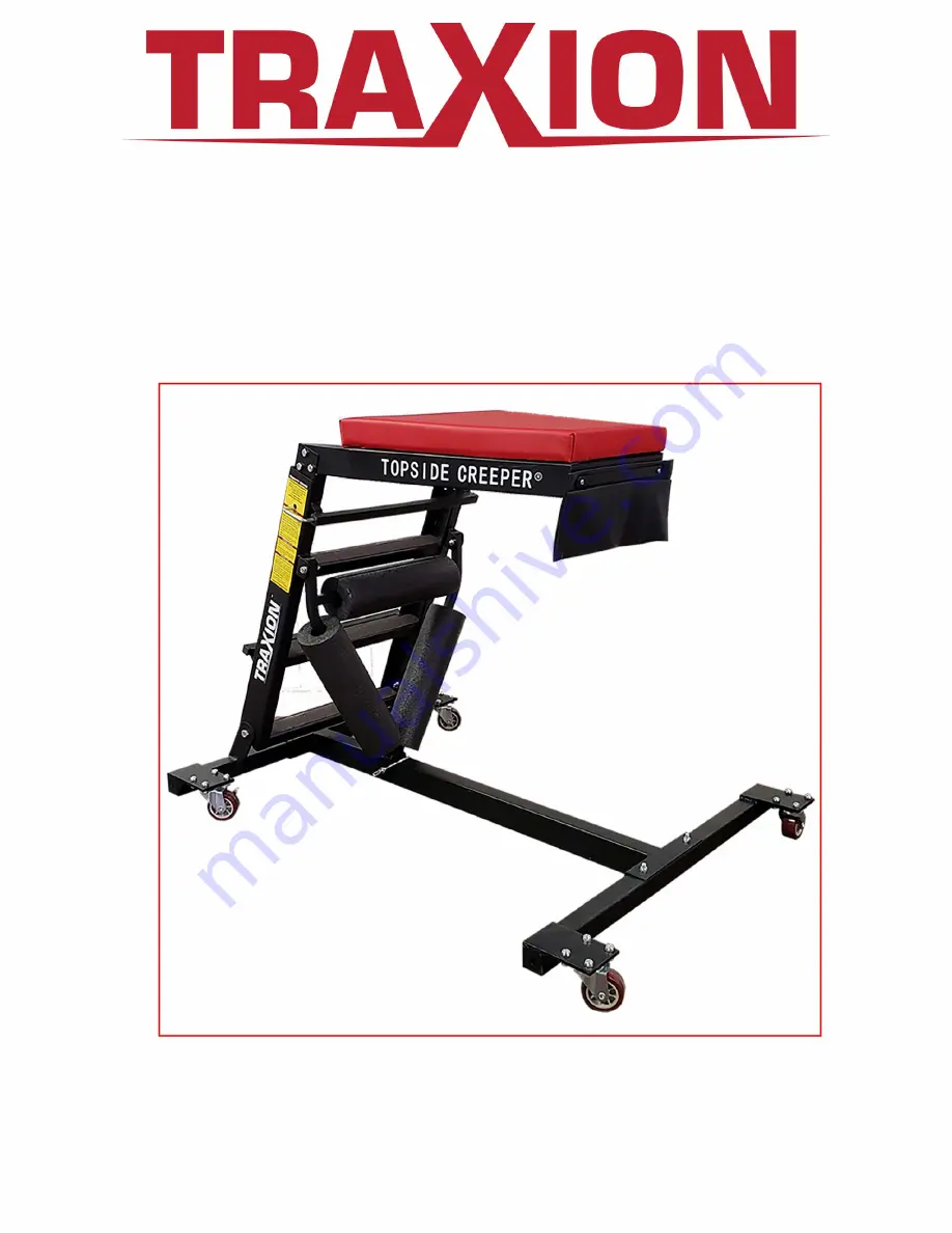
manualshive.com logo in svg
background image

engineered products 

Topside Creeper 

Shorty 

Thank you for purchasing  this Topside Creeper Shorty. 

If you have any questions or comments please 

visit our website at www.traxionproducts.com 

or phone 479-474-3460. 

©  2019  All  Rights  Reserved 

Part  No.  3-104 

Содержание Topside Creeper Shorty

Страница 1: ...side Creeper Shorty Thank you for pu rchasing this Topside Creeper Shorty If you have any questions or comments please visit our website at www traxionproducts com or phone 479 474 3460 2019 All Rights Reserved Part No 3 104 ...

Страница 2: ...Creeper Shorty Parts List I Beam x1 Front Beam x1 Back Beam x1 Ladder Housing x1 Ladder x1 Required Tools 13mm Wrench 17mm Wrench F 13mm Nut x Short 13mm Bolt x Long 13mm Bolt x4 Medium 13mm Bolt x Lock Pin x1 ...

Страница 3: ...K L 0 17mm Nutx2 p 17mm Boltx2 Casterx1 Locking Casterx1 Pouchx1 Pouch Barx1 Pad Housingx1 Foam Tubex3 6mm Phillips Screwx Padx1 6mm Nutx2 ...

Страница 4: ...e towards the rest of the I beam as shown by the red circles H x2 Next take the back bar C and insert it into the other side of the I beam A The caster sockets should face away from the front beam as shown by the red circles H x2 Next attach the I beam and front bar using 2x long 13mm bolts H and 2x 13mm nuts F Make sure to tighten the bolts enough so that the front bar has no wiggle room Finally ...

Страница 5: ...ttach it with 4x 13mm medium bolts I and 4x 13mm nuts F repeat this step for both sides of the back beam C K Line up a locking caster L with its mount on the front beam B and attach it with 4x 13mm medium bolts I and 4x 13mm nuts F repeat this step for both sides of L the front beam B ...

Страница 6: ... the front beam with one hand and with the other extend and line up the support beam and the hole on the i beam and insert the lock pin J as shown Secure the ladder housing with 2x 17mm bolts P and 2x 17mm nuts 0 one of each for each side as shown in the image below Be sure that these bolts are tight but make sure that the housing can still move without difficulty for storage purposes ...

Страница 7: ...s idnicated by the red circles To secure the ladder move it to your de sired height and insert the housing s springbar fasteners into the hole and move the ladder to the nearest setting when the springbars are in place the ladder should not be able to slide into different sockets This process can be seen in the images below ...

Страница 8: ...d sit flush with it Next attach the two pieces using 3x 13mm short bolts G and 3x 13mm nuts F on each side making for 6 bolts and 6 nuts in total 0 Attach Pouch Feed 2x Phi11ips screws T through the pouch bar R and then the pouch Q and attach it to the pad housing M using 2x 6mm bolts ...

Страница 9: ... one each side To make this process easier put the screws in loosely and then tighten them once everything is in place N Cl Attach Foam Tubes Finally attach the three foam tubes S to the ladder housing as shown in the image below The tubes have slits that allow you to slide them onto the housing you may have to apply a bit of force to get the slits to open wide enough ...

Отзывы: