background image

46 

Limted 7 Year Warranty 

© Travis Industries 

4091008 

100-01236_000 

Register your TRAVIS INDUSTRIES, INC. Limited 7 Year Warranty online at 

traviswarranty.com

, or complete the enclosed Warranty card and mail it within 

ten 

(10)

 days of the appliance purchase date to: TRAVIS INDUSTRIES, INC., 4800 Harbour Pointe Blvd. SW, Mukilteo, WA  98275.  TRAVIS INDUSTRIES, INC. 

warrants this gas appliance (appliance is defined as the equipment manufactured by Travis Industries, Inc.) to be defect-free in material and workmanship to the 
original purchaser from the date of purchase as follows: 

Check with your dealer in advance for any costs to you when arranging a warranty call.   

Mileage or service charges are not covered by this warranty. This charge can vary from store to store. 

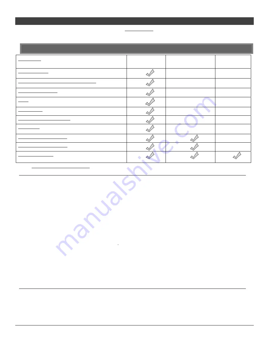
Component 

Years 1 & 2 

Parts & Labor 

Years 3 Through 5 

Parts & Labor 

Years 6 & 7 

Parts Only 

Burner Assembly 

Burner Pan Assembly, Air Shutter Assembly, Main Burner Orifice 


Electrical Assembly (within heater structure): 

Wiring harness, snap discs, rheostat speed control


Gas Control Assembly 

ustable control valve, fireplace controller, pilot assembly and pilot wiring 


Glass 

Glass (breakage from thermal shock) 


Ceramic Logs 

Log Set, Embers


Gold, Nickel & Copper Plating 

Face & Door (see “Conditions and Exclusions” # 9)


Accessories 

Firebacks, Power Heat Ducts, Andirons, etc… 


One-Way Freight Allowance 

One-way freight allowance on pre-authorized repair done at factory is covered.


Convection Heat Exchanger 

Convection heat exchanger assembly


Firebox Assembly 

Adjustable Air Restrictor, Pressure Relief Mechanisms, Glass Attachment Mechanism


EXCLUDED COMPONENTS: 

Paint, Gasketing, and Accent Light Bulbs 

CONDITIONS & EXCLUSIONS 

1.  This new gas appliance must be installed by a qualified gas appliance technician.  It must be installed, operated, and maintained at all times in accordance with the instructions in the Owner’s 

Manual.  Any alteration, willful abuse, accident, neglect, or misuse of the product shall nullify this warranty. 

2.  This warranty is nontransferable, and is made to the ORIGINAL purchaser, provided that the purchase was made through an authorized TRAVIS dealer. 
3.  Discoloration and some minor expansion, contraction, or movement of certain parts and resulting noise, is normal and not a defect and, therefore, not covered under warranty.  The installer must 

ensure the appliance is burning as per the rating tag at the time of installation.  Over-firing (operation above the listed BTU rate) of this appliance can cause serious damage and will nullify this 
warranty.  

4.  The warranty, as outlined within this document, does not apply to the chimney components or other Non-Travis accessories used in conjunction with the installation of this product. If in doubt as to 

the extent of this warranty, contact your authorized TRAVIS retailer before installation.   

5.  Travis Industries will not be responsible for inadequate performance caused by environmental conditions such as nearby trees, buildings, roof tops, wind, hills or mountains or negative pressure or 

other influences from mechanical systems such as furnaces, fans, clothes dryers, etc. 

6.  This Warranty is void if: 
a.  The unit has been operated in atmospheres contaminated by chlorine, fluorine or other damaging chemicals. 
b.  The unit is subject to submersion in water or prolonged periods of dampness or condensation. 
c.  Any damage to the unit, combustion chamber, heat exchanger or other components due to water, or weather damage which is the result of, but not limited to, improper chimney/venting installation. 
7.  Exclusions to this 7 Year Warranty include:  injury, loss of use, damage, failure to function due to accident, negligence, misuse, improper installation, alteration or adjustment of the manufacturer's 

settings of components, lack of proper and regular maintenance, damage incurred while the appliance is in transit, alteration, or act of God. 

8.  This 7 Year warranty excludes damage caused by normal wear and tear, such as paint discoloration or chipping, worn or torn gasketing, corroded or cracked logs, embers, etc.  Also excluded is 

damage to the unit caused by abuse, improper installation, modification of the unit, drilling of the orifices, or the use of fuel other than  that for which the unit is configured.  Units are shipped for 
natural gas and must be converted to propane using a conversion kit.  Confirm fuel configuration with your installer.   

9.  Damage to gold or nickel surfaces caused by fingerprints, scratches, melted items , or other external sources left on the gold or nickel  from the use of cleaners other than denatured alcohol  is not 

covered in this warranty. 

10. TRAVIS INDUSTRIES, INC. is free of liability for any damages caused by the appliance, as well as inconvenience expenses and materials.  Incidental or consequential damages are not covered by 

this warranty.  In some states, the exclusion of incidental or consequential damage may not apply. 

11. This warranty does not cover any loss or damage incurred by the use or removal of any component or apparatus to or from the gas appliance without the express written permission of TRAVIS 

INDUSTRIES, INC.  and bearing a TRAVIS INDUSTRIES, INC. label of approval. 

12. Any statement or representation of TRAVIS products and their performance contained in TRAVIS advertising, packaging literature, or printed material is not part of this 7 year warranty. 
13. This warranty is automatically voided if the appliance’s serial number has been removed or altered in any way. If the appliance is used for commercial purposes, it is excluded from this warranty. 
14. No dealer, distributor, or similar person has the authority to represent or warrant TRAVIS products beyond the terms contained within this warranty.  TRAVIS INDUSTRIES, INC. assumes no liability 

for such warranties or representations. 

15. Travis Industries will not cover the cost of the removal or re-installation of hearths, facing, mantels, venting or other components. 
16. If for any reason any section of this warranty is declared invalid, the balance of the warranty remains in effect and all other clauses shall remain in effect. 
17. THIS 7 YEAR WARRANTY IS THE ONLY WARRANTY SUPPLIED BY TRAVIS INDUSTRIES, INC., THE MANUFACTURER OF THE  APPLIANCE.  ALL OTHER WARRANTIES, WHETHER 

EXPRESS OR IMPLIED, ARE HEREBY EXPRESSLY DISCLAIMED AND PURCHASER’S RECOURSE IS EXPRESSLY LIMITED TO THE WARRANTIES SET FORTH HEREIN. 

IF WARRANTY SERVICE IS NEEDED: 

1.  If you discover a problem that you believe is covered by this warranty, you MUST REPORT it to your TRAVIS dealer WITHIN 30 DAYS, giving them proof of purchase, the purchase date, and the 

model name and serial number. 

2.  Travis Industries has the option of either repairing or replacing the defective component.  
3.  If your dealer is unable to repair your appliance’s defect, he may process a warranty claim through TRAVIS INDUSTRIES, INC., including the name of the dealership where you purchased the 

appliance, a copy of your receipt showing the date of the appliance’s purchase, and the serial number on your appliance.  At that time, you may be asked to ship your appliance, freight charges 
prepaid, to TRAVIS INDUSTRIES, INC.  TRAVIS INDUSTRIES, INC., at its option, will repair or replace, free of charge, your TRAVIS appliance if it is found to be defective in material or 
workmanship within the time frame stated within this 7 year warranty.  TRAVIS INDUSTRIES, INC. will return your appliance, freight charges (years 1 to 5) prepaid by TRAVIS INDUSTRIES, INC., to 
your regional distributor, or dealership. 

4.  Check with your dealer in advance for any costs to you when arranging a warranty call.  Mileage or service charges are not covered by this warranty. This charge can vary from store to store. 

Содержание DVL GSR Insert

Страница 1: ...t use any phone in your building Immediately call gas supplier from a neighbor s phone Follow the gas supplier s instructions If you cannot reach your gas supplier call the fire department Installatio...

Страница 2: ...L Insert has the same serial number as yours The serial number is below and to the left of the gas control valve This serial number will be needed in case you require service of any type Model DVL Ins...

Страница 3: ...r Log Placement 23 Left Log Placement 24 Right Log Placement 24 Left Twig Placement 25 Right Twig Placement 25 Front Ember Chunk Placement 26 Rockwool Installation 27 Steps for Finalizing the Installa...

Страница 4: ...ty hazard Direct questions about the type of fuel used to your dealer Check for a label on the flame adjust knob on the gas control valve this is the best place to check You may also check for a label...

Страница 5: ...urn the gas off at the gas control valve and call your dealer for service Instruct everyone in the house how to shut gas off to the appliance and at the gas main shutoff valve The gas main shutoff val...

Страница 6: ...00 600 to 2 000 Maximum BTU Input Per Hour 40 000 40 000 Heating capacity will vary with floor plan insulation and outside temperature Dimensions 40 4x6 Panels 44 3 16 8x10 Panels 48 3 16 10x13 Panels...

Страница 7: ...below are divided into sections All requirements must be met simultaneously The order of installation is not rigid the qualified installer should follow the procedure best suited for the installation...

Страница 8: ...llation This heater may be placed in a bedroom Please be aware of the large amount of heat this appliance produces when determining a location a b c e f g d h Fireplace Sizing 3 Piece Panel 1 Piece Pa...

Страница 9: ...e members must not be removed or altered side and top of door frame side and top of the face of the fireplace metal sides etc The metal floor J may be removed to allow additional room for installation...

Страница 10: ...ntel combustible or non combustible 35 5 902mm x Hearth Extension 3 Piece Panel 1 25 32mm x Hearth Extension 1 Piece Panel 0 0mm Measured from the base of the insert NOTE the non combustible top facin...

Страница 11: ...se the new mounting brackets either included with the heater or available through your dealer SKU 225 20054 WARNING When attaching the Victorian Lace Face do not over tighten the screws Over tightenin...

Страница 12: ...ply piping by closing the manual shutoff valve Leak test all gas line joints and the gas control valve prior to and after starting the heater This heater is designed either for natural gas or for prop...

Страница 13: ...e above the chimney top Be careful not to crimp or rupture the liner when bending it into chimney offsets When installed the vent must meet all of the vent manufacturer s requirements Make sure to use...

Страница 14: ...tor To Access the Restrictor This restrictor is in position 1 factory setting This restrictor is in position 2 Adjustment Bracket To adjust lift up on the adjustment plate and push it back use pliers...

Страница 15: ...ocation forward toward the fireplace opening approximately 1 4 Vent Configurations Z C Metal Wood Burning Fireplace Inlet Exhaust Re Line Exhaust Only Re Line Direct Vent Cap part 991 Recommended Bloc...

Страница 16: ...emove the vent connector and attach it to the flex vent see the instructions on the following page NOTE be careful of the anti seize on the connector it will stain clothing etc 3 Pull on the flex vent...

Страница 17: ...Attach the flex vent to the vent connector Slide the insert into place lining up these guides with the edges of the vent connector Push the vent connector rod in lift slightly and line it up so the t...

Страница 18: ...a Run the power cord to the right of the insert Top Panel Top Trim L Bracket Right Side Trim L Bracket Right Side Trim Top Trim Trim Installation Insert one leg of each L bracket into the top and side...

Страница 19: ...7200315 to route power to the insert Otherwise route the power cord behind the panel to the right side the panel or fireplace may be notched if required Installation 1 Attach the mounting brackets as...

Страница 20: ...20 Installation for qualified installers only Travis Industries 4091008 100 01236_000 2 Attach the surround panel as shown below...

Страница 21: ...the right a Glass Frame Lift the glass frame up and pull it forward to remove NOTE You may need to lift the glass frame while re attaching b Re Attaching the Glass Frame a Hang the glass frame on the...

Страница 22: ...latch is turned 1 8 turn when disengaged from the unit Follow the directions below to re install the latch if it comes loose Glass Hold the latch at an angle and insert it into the slot on the glass f...

Страница 23: ...If using propane LP convert the appliance before installing the logs see page 47 The burner must be correctly positioned before installing the logs Make sure the burner is fully seated and the pilot...

Страница 24: ...e on the log see photos below Position the log so the right side straddles the burner holes The log must not cover any burner holes Right Log Placement The right log has a hole on the bottom Place the...

Страница 25: ...two holes in the bottom that fit over the pins on the back and left log see photos below Place the twig as shown below Right Twig Placement The right twig has one hole in the bottom that fits over the...

Страница 26: ...inalizing the Installation Travis Industries 4091008 100 01236_000 Front Ember Chunk Placement Place the ember chunk as shown in the photos below Make sure the ember chunks does not cover any burner h...

Страница 27: ...ble edges of the burner Rockwool Installation The included rock wool is placed on top of the burner to enhance the glow from the burner The rock wool works best when it is applied in a very thin porou...

Страница 28: ...er cover included in the owner s pack see illustration below The AA batteries act as a power backup in case the household AC power goes out and are required for operation Install the 9v battery includ...

Страница 29: ...blue and short close the air shutter Too Much Air Swing the control cover down to access the air shutters Front Burner Air Shutter Control RED Left Less Air Right More Air Rear Burner Air Shutter Cont...

Страница 30: ...so supplies low voltage for the fireplace controller By leaving it in the OFF position the fireplace will operate off the receiver batteries greatly diminishing battery life Figure 1 Synchronize the T...

Страница 31: ...om Condensation may appear on the glass each time you start the heater this is normal Blue Flames will occur on the heater when it first comes on After fifteen minutes the flames will turn a more real...

Страница 32: ...is controlled by the transmitter ON REMOTE OFF PRG Figure 3 NOTE When the receiver switch is turned to ON or OFF the mode settings Accent Light Blower Flame Height Comfort Control will remain in the s...

Страница 33: ...d conditions you may notice that the burner does not light quickly and the flames lift off the burner If this is situation we recommend you switch to continuous pilot This will create a slight draft i...

Страница 34: ...AX Thermostat Display Room Temperature Display Read Out Thermostat Setting Function etc Mode Display Flame Height Blower Light Comfort Control Figure 4 Listen for the Beep Each time you press a button...

Страница 35: ...operation without turning the burner on and off also called smart modulation To adjust the target temperature press the up and down buttons until a suitable temperature is achieved F AUX MAX When in s...

Страница 36: ...OFF F AUX MAX When in flame height mode this icon will appear darkened MAX This is the flame height read out Use the up or down buttons to adjust the flame height 7 settings High Medium Off Figure 10...

Страница 37: ...ostat on the heater must be turned on for remote operation to work correctly You may wish to adjust the rheostat to a desirable light output prior to operating HINT If you wish to leave the accent lig...

Страница 38: ...occurs see Receiver Battery Installation on page 40 In applications where the appliance is required to provide heat we recommend replacing the batteries before each heating season Child Proof Feature...

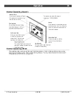
Страница 39: ...has an optional blower to push heated air into the room You will hear the sound of air movement that increases as the speed is increased Extinction Pops It is not unusual especially on Propane LP appl...

Страница 40: ...hese batteries control the comfort control and act as a power backup in case the household AC current goes out Control Panel Light Battery LED lights and a 9v battery are used to illuminate the contro...

Страница 41: ...for sooting A small amount of soot along the bottom of the logs is normal If excessive sooting is found the heater will require adjustment Contact your dealer 4 Inspect the burner and remove any debr...

Страница 42: ...sure standing pilot is off then turn back on Contact your dealer if this occurs Thermostat Does Not Work The receiver is turned to OFF The thermostat is set too low Turn the receiver switch to ON Che...

Страница 43: ...N2 GROUND VALVE COMMAND POWER CN1 DIAGNOSTIC CN0 White Blue Yellow Green Orange VALVE IPI CPI TOP 4 AA Batteries Remote Receiver Fan Controller 110V OUT FAN AUX OUT COM POWER STEPPER MOTOR BURNER CONT...

Страница 44: ...is Industries replacement parts Do not use substitute materials Warning Do not operate appliance with the glass front removed cracked or broken Replacement of the glass should be done by a licensed or...

Страница 45: ...Safety Label 45 Travis Industries 4091008 100 01236_000 Safety Label The safety listing label is attached to the operating tag chained to the heater near the gas control valve A copy is shown below...

Страница 46: ...nents lack of proper and regular maintenance damage incurred while the appliance is in transit alteration or act of God 8 This 7 Year warranty excludes damage caused by normal wear and tear such as pa...

Страница 47: ...ench and pilot orifice The burner orifices are shipped with the appliance Convert the appliance prior to installing the gas line to ensure proper gas use 1 Remove the glass see page 21 Remove the logs...

Страница 48: ...cating full insertion c Look here for the orifice identification Apply thread sealant to the LP orifices prior to installation Use the chart below to identify the correct orifices Front Rear NG 49 43...

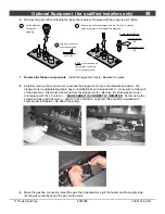
Страница 49: ...Replace the firebox components Install the logs and embers Replace the glass 8 Carefully remove the control cover to access the stepper motor see the illustrations below The stepper motor adjustable r...

Страница 50: ...panel following the directions below Use the larger DVL Insert Bracket Lower Panel Top Clip Use tape to secure the clips to the bracket you may also wedge the clips into place This holds the clips in...

Страница 51: ...Optional Equipment for qualified installers only 51 Travis Industries 4091008 100 01236_000...

Страница 52: ...Hearth Requirements 9 Heating Specifications 6 Installation Options 6 Installation Warnings 7 Items Packed with the Face 7 Leveling Bolts 9 Location of Controls 30 Log Set Installation 22 Low Battery...

Отзывы: