background image


This document is intended for Public Distribution                                                  19473 Fraser Way 

Pitt Meadows, B.C. Canada V3Y 2V4 

Phone (604) 460-6002 Fax (604) 460-6005 


  8 


  www.tranzeo.com 

1/10/2006 

Q

UICK

 S

TART

 G

UIDE

 – TR-6000 

SERIES


Step 8 


Attaching the Mounting Bracket 


Grounding the Antenna 

Using a #6 Green grounding wire, connect the Grounding Lug on the radio to a proper ground. See 
APPENDIX A Lighting Information for more information. 

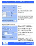
Place the Ethernet boot over the 4 Screw Posts.  
Apply 4 Kept nuts to the screw posts and tighten 
until the gasket makes full contact with the 
Ethernet boot.  The gasket should be at least 
50% compressed. 

As shown below, the U-Bolt is designed to mount 
around a pole.    Tighten bolts sufficiently to  
prevent any movement.   

Down or up tilt can be adjusted by swinging the 
unit before tightening the U-Bolt. 

Optional dual port boot specific note. 

If you are not going to be using the second port 
make sure that it is tightened down to ensure a 
weather-tight seal. 

Содержание TR-6000 Series

Страница 1: ...QUICK START GUIDE FOR THE TRANZEO WIRELESS TR 6000 SERIES REVISION 2 0a JANUARY 2ND 2006 ...

Страница 2: ...where a distance of 40 cm from the antenna may be maintained 2 While installing the antenna do not turn on power to the unit 3 Do not connect the antenna while the device is in operation 4 The antenna used for this transmitter must not be co located or operating in conjunction with any other antenna or transmitter Safety Notices Safety Precautions YOU MUST READ AND UNDERSTAND THE FOLLOWING SAFETY ...

Страница 3: ...lity as well as WEP and WPA security Maximize network efficiency while minimizing your network investment and maintenance costs TR AP Quick Start Guide Hardware Installation Product Kit Before installation make sure that you have the following items The TR 6000 series x 1 DC Power Adapter x 1 Power over Ethernet Adapter x 1 Ethernet Boot x 1 Mounting Bracket x 1 Kept Nuts With Washer Attached x 8 ...

Страница 4: ...y ONLY use the power adapter supplied with the TR 6000 series Otherwise the product may be damaged Label Color Indicators POWER Red On Powered On Off No Power LAN Green On Ethernet Link Flashing Ethernet Traffic Off No Ethernet Link Radio Amber On Radio Link Flashing Radio Activity Off No Radio Link Signal Red Amber Green In CPE mode light up in sequence to indicate signal strength Color Indicator...

Страница 5: ...ou should perform a Site Survey to determine the optimal location Ensure the CPE is within line of sight of the Access Point Obstructions may impede performance of the unit Tools Required to Install One 3 8 wrench One 3 4 wrench One RJ 45 crimper A suitable length of Cat 5 cable to bring the signal from the unit to the Power over Ethernet Adaptor 2 RJ 45 Jacks Before installing you must determine ...

Страница 6: ...2006 QUICK START GUIDE TR 6000 SERIES Connecting the Ethernet Cable Step 1 Step 2 Step 3 Place the Ethernet Boot Cover over the end of your Cat 5 cable Attach Ethernet Cable Lock on side of the Ethernet Boot This is easiest to do before you attach the RJ 45 Jack Tighten using a wrench or socket Tighten until the Cable Lock touches the Boot as shown in Step 3 ...

Страница 7: ...aling Gasket over screws Insert the Cat 5 Cable and tighten the Boot Cover Be sure to pull enough cable through to reach the RJ 45 connector with an RJ 45 jack at tached The Gasket must be attached to the Boot so that it sits between the radio and the boot Hand tighten only DO NOT OVERTIGHTEN as you may damage the environment seal Remove gasket backing and place boot cover on radio This will ensur...

Страница 8: ...rmation for more information Place the Ethernet boot over the 4 Screw Posts Apply 4 Kept nuts to the screw posts and tighten until the gasket makes full contact with the Ethernet boot The gasket should be at least 50 compressed As shown below the U Bolt is designed to mount around a pole Tighten bolts sufficiently to prevent any movement Down or up tilt can be adjusted by swinging the unit before ...

Страница 9: ...ty to additional devices This allows for the daisy chaining of multiple devices together Connect the power adapter to the power socket on the Power over Ethernet Adaptor POE and plug the other end of the power into an electrical outlet Plug the RJ 45 Ca ble from the unit into the POE The Station Adaptor will be powered on and the power indicator on the top panel will turn on NOTE ONLY use the powe...

Страница 10: ...d is default Passwords Information When you first enter the Web Interface you will be required to enter a new recovery password This password is intended to allow the ISP to change the password of the device if they forget it This password must be different than the operator password Neither password can be left at default These passwords must be changed to access the device If you do not enter ne...

Страница 11: ...ACK timing if required Beacon Interval Sets the rate at which the AP will broadcast its beacons DTIM Interval Sets the DTIM Delivery Traffic Indication Message Interval Helps to keep marginal clients connected by sending wake up frames Burst Time Sets the Burst Time in ms which will be used to send data without stopping Note that other wireless devices in that network will not be able to transmit ...

Страница 12: ... the password for accessing the device Ext Info Enabled Enable extended information Extended information is only displayed with Tranzeo Wireless Technologies Access Points Signal Status LEDs Un select to turn off the LEDs on the unit SMNP Parameters Here you set the Read Community string and Contact Location data It is highly recommended that you change the SNMP Read Community string immediately t...

Страница 13: ...throughput is need a dedicated PxP link should be used However in areas of low density WDS can allow an ISP to extend coverage into an area at very low cost Enabled Select this box to enable WDS HOW TO SET UP WDS Default the Unit to factory settings Check the Wireless Settings of the APs SSIDs can be different but the Channels MUST be the same Under the WDS settings add in the MAC address of the P...

Страница 14: ...ncryption NOTE 64 bit is referred to as 40 bit on some systems Default Key Choose the default WEP key Activate Keys Enter your WEP keys NOTE Keys must be entered in HEX only Enabled Turn On WPA Cipher Type Select the Level of Encryption TKIP or AES PSK Enter your password Update Interval Enter the update interval Enabled Turn on 802 1x RADIUS Server Au thentication RADIUS Server IP Address Enter t...

Страница 15: ...f a client and then click add to associate with it Changes to Access Control NOTE If you are working via a radio link the first MAC you should add is the address of the station you are connecting from Otherwise you will lock yourself out of the radio 1 The Manually Authorize Stations section allows you to enter a long list of MAC address 2 You can also select specific station that are already auth...

Страница 16: ...This name will be retained However if the Extended Info is turned on at the client the name will be overwritten with the name on the client The third column is the IP address As with the name if the client supplies it via the Extended Info option it will appear Otherwise you can manually enter it The fourth column in is the Status field The fifth column is the RF power in dBm as detected at the AP...

Страница 17: ... 10 2006 QUICK START GUIDE TR 6000 SERIES ARP Table This feature was added as a troubleshooting screen It shows the devices which have sent either a broadcast or directly tried to communicate with the device Under normal circumstances there should be a limited number of entries in this table especially if you have interstation blocking turned on at the AP ...

Страница 18: ...vice the radio is connecting can not support 100 Half you should replace the device or place a switch in line Network Configuration Router Mode You can choose Static DHCP or PPPoE Client IP configuration for the device Each of these options are explained on the following pages Note If you select DHCP and a DHCP server is not present the device will try to get an IP for up to 5 minutes At the end o...

Страница 19: ...umber of Addresses The number of addresses you want to have in the DHCP pool Gateway Select This Unit to use the gate way set on the WAN interface of the radio or select Other to set a different gateway address DNS WAN Assigned Select to use the DNS server addresses as assigned on the WAN side Static Select to set DNS servers if different than those on the WAN side Note If you select this option b...

Страница 20: ...ress or network that the packets will be attempting to access Subnet Mask Used to specify which portion of the Destination IP signifies the network trying to be accessed and which part signifies the host that the packets will be routed to Note 255 255 255 255 is used to signify only the host that was entered in the Destination IP field Gateway Specifies the next hop to be taken if this route is us...

Страница 21: ... the various options Enabled You must select enabled to turn the rule on Priority The lower the number the higher it priority 0 is the highest priority and 255 in lowest Name The name here is for your reference only Protocol Enter the IP Protocol Number Common options are 0 for ANY 1 for ICMP 6 for TCP and 17 for UDP See Appendix A IP Protocol numbers Source IP Range Enter the range of the IP Addr...

Страница 22: ...n the device is in Cloning MAC mode it can only be managed from the LAN side of the device Port Management Port Forwarding This is a new feature It allows the radio to forward requests for certain ports to devices behind the router For example the customer has a webserver behind the Radio on a Private Ip that they want to have accessable to the world then you can port forward all requests on Port ...

Страница 23: ...the outside world you would 1 Click Add 2 Select Deny 3 Select Source IP Range Assuming that the clients are on 192 168 1 0 24 then the source IP would be 192 168 1 1 to 192 168 1 254 4 Select Desintination IP Range Assuming that the entire outside world was to be blocked then 0 0 0 0 should entered 0 0 0 0 indictes all IP s 5 Select Source Port Range In this case enter 0 for all Ports 6 Ignore IC...

Страница 24: ...t is a Tranzeo TR 6000 series series AP with the Extended Info turned on in the Administrative Settings Window Receiving This box displays the current signal and the Lowest and Highest values For the most accurate readings data must be transmitted through the unit Transmission This box displays the current signal traffic breakdown For the most accurate readings data must be transmitted through the...

Страница 25: ...e intended for use by Tranzeo Wireless Technical Support Technical Info UMAC or Upper MAC functions occur in the Unit s Processor LMAC or Lower MAC functions occur in the Radio Chipset You can click onto each speed level and see how the traffic breaks down In the TX statistics there should little to no Tries at Series 2 3 or 4 The radio will try to send a packet 4 times at Series 1 and then tries ...

Страница 26: ...2 3 or 4 Life Statistics are reset on each reboot In the Ethernet Statistics screen excessive collisions are usually a sign that the radio and the device it is linked to are not on the same Duplex options One is at full while the other is at half Try locking both to the same values Collisions do normally occur on an Ethernet network and are generally handled by the Carrier Sense Multiple Access wi...

Страница 27: ...MR or CAT5 bad The myth is that lighting follows the path of least resistance It actually follows the path of least impedance Coiling cables creates an air wound transformer which lowers the impedance This means you are in fact making your radios a more appealing target for surges What standard does Tranzeo Wireless equipment meet This radio exceeds International Standard IEC 61000 4 5 when proper...

Страница 28: ...8 www tranzeo com 1 10 2006 QUICK START GUIDE TR 6000 SERIES Ungrounded Radio Grounded Radio Antenna POE Radio Ground An ungrounded radio causes the surge to pass through the radio In this case the radio most likely will be damaged POE Antenna Radio Ground A grounded radio causes the surge to pass directly to ground bypassing the radio ...

Страница 29: ...ES Cat 5 Cable POE In this case the surge will be picked up by the Cat 5 cable and since the POE is not grounded the route for the surge is through the radio to the antenna and out through the building Mounting Pole Mounting Pole In this case the surge will be picked up by the Cat 5 cable and since the POE is grounded the route for the surge is through the POE to ground Cat 5 Cable POE Ground ...

Страница 30: ...late the cable from any air surges 2 Keep all runs as straight as possible Never put a loop into the cables 3 Test all grounds to ensure that you are using a proper Ground If using a electrical socket for Ground use a socket tester such as Radio Shack 22 141 4 Buy a copy of the National Electrical Code Guide and follow it 5 If you are in doubt about the grounding at the location drive your own rod...

Страница 31: ...ely unacceptable level of 1 immediately Using the same scenario with Tranzeo Wireless Technologies QOS enabled the voice quality remains consistently high with an MOS of 4 4 and maintains that level even with multiple FTP streams Automatic Traffic Classification Tranzeo Wireless Technologies software has the capability of continually monitoring and classifying traffic on the Internet connection an...

Страница 32: ...ain a high MOS rating Tranzeo s software has the capability of continually monitoring and classifying traffic on the Internet connection and dynamically adjusting the way individual streams are handled at any point in time This enables latency sensitive traffic such as voice games or even web page requests to be given a relatively high priority As a result they are sent to their destination first ...

Страница 33: ...This document is intended for Public Distribution 19473 Fraser Way Pitt Meadows B C Canada V3Y 2V4 Phone 604 460 6002 Fax 604 460 6005 33 www tranzeo com 1 10 2006 QUICK START GUIDE TR 6000 SERIES ...

Страница 34: ...ity Payload for IPv6 51 AH Authentication Header for IPv6 52 I NLSP Integrated Net Layer Security 53 SWIPE IP with Encryption 54 NARP NBMA Address Resolution 55 MOBILE IP Mobility Decimal Keyword Protocol 56 TLSP Transport Layer Security using Kryptonet key management 57 SKIP SKIP 58 IPv6 ICMP ICMP for IPv6 59 IPv6 NoNxt No Next Header for IPv6 60 IPv6 Opts Destination Options for IPv6 61 any host...

Страница 35: ...W 80 World Wide Web KERBEROS 88 Kerberos POP3 110 TCP post office NNTP 119 USENET NFS 2049 Network File System SIP 5060 5061 SIP 108 IPComp IP Payload Compression 109 SNP Sitara Networks Protocol 110 Compaq Peer Compaq Peer Protocol 112 VRRP Virtual Router Redundancy 113 PGM PGM Reliable Transport 114 any 0 hop protocol 115 L2TP Layer Two Tunneling Protocol 116 DDX D II Data Exchange DDX 117 IATP ...

Отзывы: