background image

Transition Networks 


SDSTX3110-121S-LRT User Guide 

33745 Rev. A 

https://www.transition.com


Page 

15

 of 

109


3. Hardware Installation 

3.1 DIN-Rail Installation 

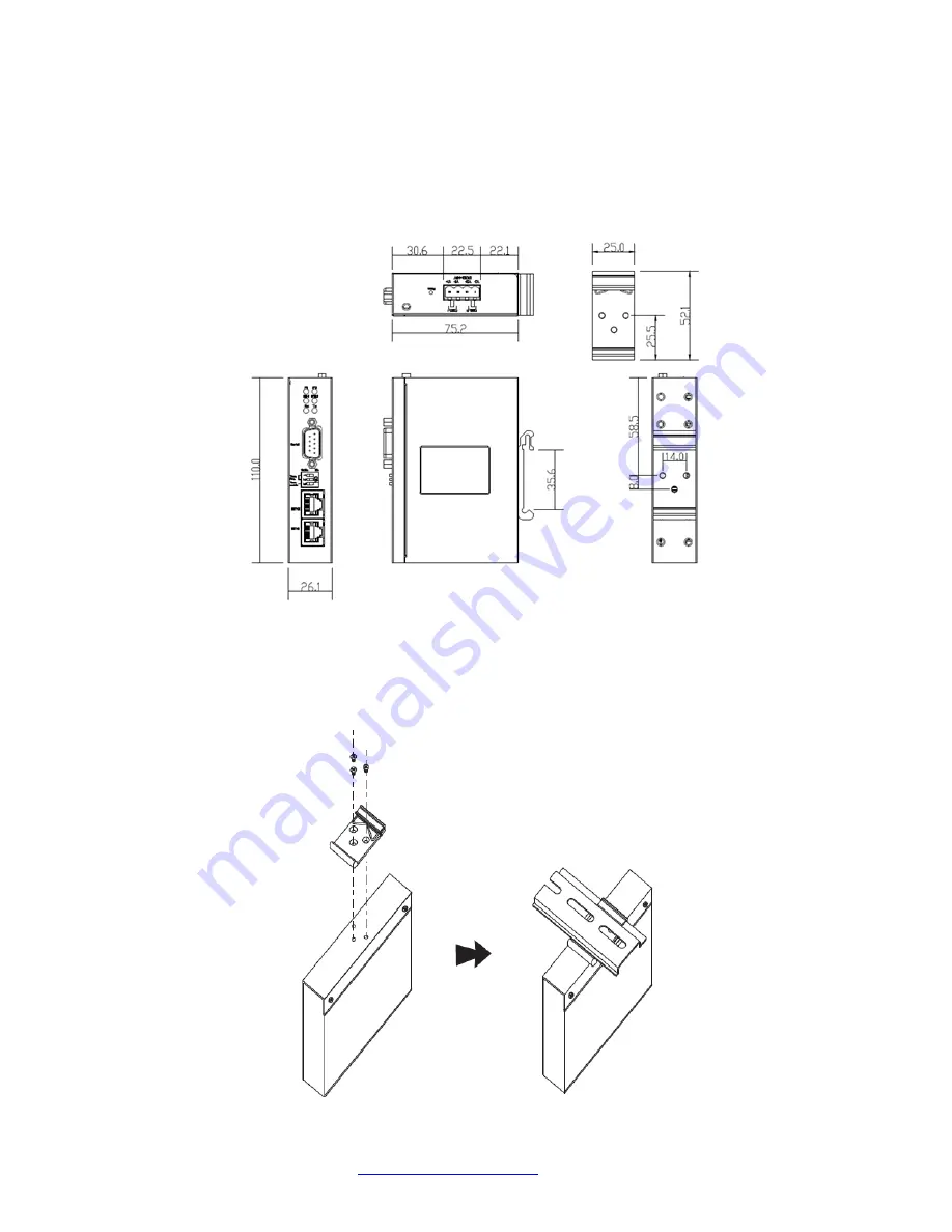
A DIN-Rail kit is pre-installed to let you fasten the device to a DIN rail. The dimensions are provided below. 


SDSTX3110-121S-LRT Dimensions (in mm) 

1. Slant the device and screw the DIN-Rail Kit onto the back of the device, right in the middle of the back panel. 
2. Slide the device onto a DIN-rail from the DIN-Rail kit and make sure the device clicks into the rail firmly. 


Содержание SDSTX3110-121S-LRT

Страница 1: ...Transition Networks SDSTX3110 121S LRT User Guide 33745 Rev A https www transition com Page 1 of 109 SDSTX3110 121S LRT Industrial Serial Device Server User Guide 33745 Rev A ...

Страница 2: ...n Networks Inc All rights reserved No part of this work may be reproduced or used in any form or by any means graphic electronic or mechanical without written permission from Transition Networks SDSTX3110 121S LRT Industrial Serial Device Server User Guide 33745 Rev A Contact Information Transition Networks 10900 Red Circle Drive Minnetonka MN 55343 USA Tel 952 941 7600 or 1 800 526 9267 Fax 952 9...

Страница 3: ...1 Front Panel 12 2 1 1 Ports and Connectors 12 2 1 4 LED Descriptions 12 2 1 6 DIP Switch for RS 422 485 Termination 13 2 2 Top Panel 14 2 3 Back Panel 14 3 Hardware Installation 15 3 1 DIN Rail Installation 15 3 2 Wall Mounting 16 3 3 Rack Mounting 17 3 4 Wiring 18 3 4 1 Grounding 18 3 4 2 Redundant Power Inputs 18 3 5 Connection 19 3 5 1 10 100BASE T X Pin Assignments 19 3 5 2 Cable Types and Sp...

Страница 4: ...boot 65 4 5 Configuration by SSH Console 74 4 5 1 Connect to SSH Console 74 4 6 Uninstall SDS Manager 87 5 Technical Specifications 89 SDSTX3110 121S LRT Regulatory Approvals 90 Power Supply Specifications 91 xxxxx GlobTek Power Supply 91 25130 Features and Specifications 94 25135 Features and Specifications 96 6 Troubleshooting 98 6 1 FAQs 98 6 2 Procedure 99 6 3 Record Model and System Informati...

Страница 5: ...raining cabinets The device accepts 12 48VDC power input and it is also certified to operate in temperatures of 40 C to 70 C 1 1 Product Numbers The SDS models are described below Product Description SDSTX3110 121S LRT Slim size Industrial 1 secure serial port to Ethernet device server with one 1 RS232 422 485 DB9 ports and two 2 10 100Base TX RJ 45 ports with a reduced footprint It has 2 10 100Ba...

Страница 6: ...s 8 Windows OS support Windows NT 2000 XP 2003 VISTA 32 64bit Windows 7 32 64bit Windows 8 1 2 1 Hardware Features DIN rail and wall mount enabled Redundant DC power inputs IP Casing IP 30 Extended operating temperature 40 C to 70 C 1 2 2 Software Features Supports five host devices including Virtual COM TCP Server TCP Client modes and four IP ranges Supports application based QoS management NAT p...

Страница 7: ...121S LRT User Guide 33745 Rev A https www transition com Page 7 of 109 1 3 Applications The figure below shows typical SDS configurations e g Multiple Host PCs SSL Data Encryption TCP Client Server Modes and NAT Router Pass through ...

Страница 8: ...ition Networks SDSTX3110 121S LRT User Guide 33745 Rev A https www transition com Page 8 of 109 1 4 Dimensions 1 4 1 SDSTX3110 121S LRT Dimensions The SDSTX3110 121S LRT cabinet dimensions are provided below ...

Страница 9: ... operation modes The table below provides the DB9 connector pin assignments Pin RS 232 RS 422 RS 485 4 wire RS 485 2 wire 1 DCD TX TX DATA 2 RXD TX TX DATA 3 TXD RX RX 4 DTR RX RX 5 GND GND GND 6 DSR 7 RTS 8 CTS 9 RI DB 9 Serial Port 1 5 2 DB9 Console Port Wiring The serial ports can be connected using a DB9 cable The DB9 connector supports RS232 RS422 RS485 operation modes Please refer to the fol...

Страница 10: ...T X MDI MDI X Pin Assignments Note and signs represent the polarity of the wires that make up each wire pair Pin Number MDI port MDI X port 1 TD transmit RD receive 2 TD transmit RD receive 3 RD receive TD transmit 4 Not used Not used 5 Not used Not used 6 RD receive TD transmit 7 Not used Not used 8 Not used Not used 9 ...

Страница 11: ...ed all of the following items One SDSTX3110 121S LRT Two Wall Mount Brackets One DC Jack to 1 pair Cable Black Female D2C 2001 One TN Postcard and one printed Quick Start Guide One Plastic Bag with a 4 Pin Terminal Block two I O Dust Covers and eight Screws One optional power supply 1 7 Optional Accessories These optional accessories can be ordered separately 25130 Industrial DIN Rail Mount Power ...

Страница 12: ...e the device configurations back to the factory defaults click the front panel Reset button for a few seconds Once the power LED starts to flash release the button The device will then reboot and return to factory defaults 2 1 4 LED Descriptions With the device installed and cabled the green power LED should light The LEDs are described below LED Color State Description P1 P2 Green On Power is on ...

Страница 13: ...on accomplished by attaching a resistor between the signal lines on the extreme ends of the transmission line Set DIP switch 3 to ON enabled for long distance 100m transmission to improve the quality of data transmission The default is Off SW No Description 1 150K 1K Ohm Pull High Low Resistor 2 3 Enable Disable Terminal Resistor DIP Switch SW No Setting Description 1 Off 150K 1K Ohm Pull High Low...

Страница 14: ...op panel components are shown and described below 1 Terminal block V1 V1 V2 and V2 for power connections 2 Grounding screw see section 3 4 1 Grounding on page 18 3 Reset button SDSTX3110 121S LRT Top Panel 2 3 Back Panel Below are the back panel components with the DIN rail kit removed and with the DIN rail kit installed ...

Страница 15: ...Rail kit is pre installed to let you fasten the device to a DIN rail The dimensions are provided below SDSTX3110 121S LRT Dimensions in mm 1 Slant the device and screw the DIN Rail Kit onto the back of the device right in the middle of the back panel 2 Slide the device onto a DIN rail from the DIN Rail kit and make sure the device clicks into the rail firmly ...

Страница 16: ...clip by removing the three screws 2 Use the screws included in the package to install the wall mount bracket 3 Screw the two pieces of wall mount kits to the top and bottom panels of the device A total of eight screws are required as shown below 4 Use the device with wall mount plates attached as a guide to mark the correct locations of the four screws 5 Insert a screw head through middle of the k...

Страница 17: ... 3 3 Rack Mounting The SDS can be rack mounted using the procedure below 1 Install the provided L shaped mounting brackets to the left and right sides of the device as shown below 2 With the front brackets oriented in the front of the rack mount the device in the rack with the four rack mounting screws ...

Страница 18: ...avoid interference wires with different signal characteristics should be routed separately 6 You can use the type of signal transmitted through the wire to determine which wires should be kept separate The rule of thumb is that wiring sharing similar electrical characteristics can be bundled together 7 You should separate input wiring from output wiring 8 It is advised to label the wiring to all d...

Страница 19: ...bs See the table below for cable specifications With 10 100BASE T X cables pins 1 and 2 are used for transmitting data and pins 3 and 6 are used for receiving data Note that the and signs represent the polarity of the wires that make up each pair Pin Number Assignment 1 TD 2 TD 3 RD 4 Not used 5 Not used 6 RD 7 Not used 8 Not used 3 5 2 Cable Types and Specifications Cable Type Max Length Connecto...

Страница 20: ...it Windows systems 1 Determine which version you require 2 Download it from the Transition Networks website SDS Management Software zip file e g filename SDS Manager_x64_v1 5a_20170413 zip 3 Unzip the Zip file e g SDS Manager_x64_v1 5a_20170413 exe 4 Note the name and location of the EXE file Firmware file names have the format SDSTX3110 121S LRT_2016221_1 1_uImage SDS Manager file names are SDS M...

Страница 21: ...4 Check either the Launch SDS Manager Now checkbox or the Launch SDS Manager Later checkbox When you launch SDS Manager a confirmation message displays 5 Click Yes to restart your computer to complete the installation or select No and restart it later The SDS Manager startup screen Device List displays ...

Страница 22: ... device Save Load Apply and Save Apply all changes and save to Flash Load Default Load factory default settings except for the IP address Reboot Device Import Export Configuration Save the configuration of device as a file Import the pre saved configuration file to apply to new device 4 Go to the port menu and configure the port settings Serial Settings Configure the Port alias baud rate parity da...

Страница 23: ...ming STEP 4 Done File Serial Tunnel Wizard helps you couple two serial devices to directly communicate by Ethernet without the PC STEP 1 Select two devices that should be tunneled together STEP 2 Select serial parameters such as baud rate data bits STEP 3 Finish File Group IP Wizard helps you configure the IP addresses of a group of new devices The devices already in the configuration list will no...

Страница 24: ...nfiguration Add Device by IP lets you search by Domain Name IP Range and or Management Port Number or lets you cancel the search Device Configuration Remove Device lets you remove a selected device from the configuration Device Configuration Import Device Configuration lets you import a selected device into the configuration Device Configuration Export Device Configuration lets you export a select...

Страница 25: ... Configuration Broadcast Search menu path SDS Manager will broadcast to the network and search for all available SDS devices on the network automatically The default IP address of the device is 192 168 1 77 Select the device you want to use and click the Add button You can set a static IP address or use the DHCP client mode to acquire an IP address automatically Click OK and the device will be add...

Страница 26: ...e Name Location You can input the device name or related information in this field Using SNTP Time Server To set the time via an SNTP time server check the box and input related information such as the SNTP server domain name or IP address and the port number then select a time zone SNTP Server IP Displays the current SNTP Server IP address Port Displays the currently configured port number e g po...

Страница 27: ...immediately apply the settings but not save applied settings into the flash memory of the device Apply and Save button Click the Apply and Save button immediately apply the settings and to save all applied settings into the flash memory of the device Refresh button Click the Refresh button to update the screen content undo changes made since last Save ...

Страница 28: ... Description Access IP Table You can enter the host IP addresses and network masks to prevent unauthorized access Check the Enabled checkbox to enable each IP address for access IP1 IP16 Password You can set or change the password to prevent unauthorized access from your server The factory default is no password empty field Change Password button Click the Change Password button when done User Nam...

Страница 29: ...odes Static IP or DHCP BOOTP The factory default IP address is 192 168 1 77 Wire Sub Tab Label Description Using Static IP Check the box to manually assign an IP address to the device Using DHCP BOOTP Check the box to have the IP address automatically assigned by a DHCP server in your network IP Address Enter the IP address of the serial device server Netmask All devices on the network must have t...

Страница 30: ...ng explicitly requested You must set up one or more trap servers that will receive these messages if the box is checked Email Notification Check the box to allow the system to send emails when an event occurs You must specify the SMTP Server and the email address to use for sending emails if the box is checked Syslog Notification Check the box to allow the system to send a detailed log to an exter...

Страница 31: ...ecked DSR Changed When the DSR Data Set Ready signal changes it indicates that the data communication equipment is powered off A notification will be sent if the box is checked RI Changed When the RI Ring Indicator signal changes it indicates the incoming of a call A notification will be sent if the box is checked CTS Changed When the CTS Clear To Send signal changes it indicates that the transmis...

Страница 32: ...able management from the web Click the Goto Web Management button to access the web Telnet Management Enable Check the box to enable management by Telnet Click the Goto Telnet Management button to execute Telnet commands SNMP Management Enable Check the box to enable management by SNMP SNMP Management Settings If SNMP Management Enable is checked you must fill in the SNMP settings in these fields ...

Страница 33: ...c folder Click the Upgrade button to start the upgrade process Label Description Firmware Image Provide the path and filename The firmware image is typically a bin file or a uImage file Browsing Click the button to browse to and select the desired firmware image file Upgrade Click the button to upgrade the SDS device to the selected firmware image file Refresh Click the button to update the screen...

Страница 34: ...ot Device Click this button to re boot the device you must broadcast again to search for the device warm start Import Configuration Click this button to retrieve a saved configuration file and apply it to the current device Export Configuration Click this button to save the current parameters to a file and export it to a current host At the Save As dialog browse to a Save in location enter a file ...

Страница 35: ...ort You can configure the settings for each serial port by clicking on the port number in the left pane of the window When you click on a port in the left pane the screen below displays in the right panel This page displays the Serial Settings Service Mode and Notification tabs as described and shown in the following sections ...

Страница 36: ...Parity is a simple form of error detection which guards data on the cable between the connected devices and the serial port The available Parity options include None no parity checking is performed and the parity bit is not transmitted Odd the number of mark bits in the data is counted and the parity bit is asserted or unasserted to obtain an odd number of mark bits Even the number of mark bits in...

Страница 37: ...the data itself on separate wires Interface Choose an interface for your serial device Available interfaces include RS 232 RS 422 RS 485 2 wires and RS 485 4 wires After a Virtual COM has been mapped to a port changes to the serial settings of that port e g from RS232 to RS422 should not be made Performance Throughput guarantees highest transmission speed Latency guarantees shortest response time ...

Страница 38: ...ev A https www transition com Page 38 of 109 Label Description The factory default value is 0 The received data will be queueing in TX buffer until TX interval time is timeout or TX buffer is full 4K bytes the data will also be sent The value 0 means disable ...

Страница 39: ... Number Check the checkbox to allow changing the Data Port number Control Port Displays the control port number read only Map Virtual COM Click to select a Virtual COM name to map on Validated characters of virtual COM name is A Z a z and 0 9 Max length of the name is 128 characters Select at the Select a Virtual COM Name dialog and click OK Idle Timeout When a serial port stops data transmission ...

Страница 40: ...rt will be freed 0 means the function is disabled which is also the factory default value Max Connections The number of max connections can be supported simultaneously is 5 default value is 1 Destination Host Displays one to four connected destination hosts VCOM Name Displays the related VCOM name or a message like Waiting for VCOM connect Goto VCOM Click the button to go to the related VCOM port ...

Страница 41: ... with SSL Allows encryption via Secure Socket Layer Telnet Negotiation Allows a client or a server to help provide an enhanced user experience Data Port Set the port number for data transmission Auto Scan Click to scan the data port automatically Idle Timeout When a serial port stops data transmission for a defined period of time Idle Timeout the connection will be closed and the port will be free...

Страница 42: ...nnection will be closed and the port will be freed 0 means the function is disabled which is also the factory default value Max Connections Up to 5 connections can be supported simultaneously the default value is 1 Destination Host Input the IP address of one to five destination hosts Disconnect Click to disconnect a connected destination host ...

Страница 43: ...eed and try to connect with other hosts 0 means the function is disabled which is the factory default value If multilink is configured only the first host connection is effective for this setting Alive Check The serial device will send a TCP alive check package in each defined time interval Alive Check to remote host to check the TCP connection If the TCP connection is not alive the connection wil...

Страница 44: ...ing a value in destination host IP begin end fields You can also auto scan the sending port number of the device Sending Port IP port for sending outgoing messages Messages Message Apply or Discard The settings has been changed Apply to device or discard Meaning You made changes and then left the page and are being prompted to either apply those changes or discard the changes Recovery 1 Click the ...

Страница 45: ...ect Monitor Items The VCOM List COMx Serial Settings tab displays Link Information and current serial device settings Baudrate Stop Bits Parity Flow Control Data Bits and Interface selections The VCOM List COMx Connection Settings tab displays Link Information and current serial settings Remote Device IP Port and Connection Status The VCOM List COMx Statistics tab displays Link Information and cur...

Страница 46: ...unnel Wizard Group IP Wizard Group Setup Wizard and Group Firmware Wizard 4 2 8 IP Collection The IP Collection page displays automatically collected IP address device name model last report of devices by a defined time interval 4 2 9 System Log The System log page displays current log messages of the device lets you clear the messages and lets you display messages based on a Year and Month select...

Страница 47: ...d manage your SDS via a Web browser 1 Launch a Web browser 2 At https type the default IP 192 168 1 77 and press Enter A login screen displays 3 Type the default username root Type the default password root You may set up a different user name and password later on the IP Configuration page 4 Press Enter or click OK the System Information page displays The right side of the page displays the IP Ad...

Страница 48: ...our computer system time with a server that has already been synchronized by a source such as a radio satellite receiver or modem Label Description Name Enter the model name of the device SNTP Enable or disable SNTP function Time Zone Choose the time zone according to the location of the device See the table below for details Local Time Set up the local time Time Server Enter the address of the ti...

Страница 49: ...cific Standard ADT Alaskan Daylight 8 hours 4 am ALA Alaskan Standard 9 hours 3 am HAW Hawaiian Standard 10 hours 2 am Nome Alaska 11 hours 1 am CET Central European FWT French Winter MET Middle European MEWT Middle European Winter SWT Swedish Winter 1 hours 1 pm EET Eastern European USSR Zone 1 2 hours 2 pm BT Baghdad USSR Zone 2 3 hours 3 pm ZP4 USSR Zone 3 4 hours 4 pm ZP5 USSR Zone 4 5 hours 5...

Страница 50: ...ou choose DHCP the following fields will gray out Static Enter an IP address for the device Select Static IP if you are using a fixed IP address DHCP BOOTP allows the IP address of the device to be automatically assigned by a configuration server IP Address Enter the IP address that identifies the server on the TCP IP network The default is 192 168 10 1 Netmask Enter a subnet mask for the device T...

Страница 51: ... lets you change your password Label Description User Name Enter the default User Name root in lower case Old Password Enter the existing password that is used to log in New Password Enter a new password that will be used to log in Confirm New Password Retype the new password to confirm Click the Apply button when done to apply the changes ...

Страница 52: ...Data Bits Choose the number of data bits to transmit You can configure data bits to be 7 or 8 Data is transmitted as a series of seven or eight bits five and six bit data formats are used rarely for specialized communications equipment Stop Bits Choose the number of bits used to indicate the end of a byte You can configure stop bits to be 1 or 2 1 5 If Stop Bits is 1 5 the stop bit is transferred ...

Страница 53: ...r its Tx line to tell the transmitting side to stop transmitting Choose XON to tell the computer to begin sending data again then the receiving side will send an XON character over its Tx line to tell the transmitting side to resume transmitting In hardware flow control mode when the device is ready to receive data it sends a CTS Clear To Send signal to the device on the other end When a device ha...

Страница 54: ... Serial read only Flush Data Buffer After The received data will be queuing in the buffer until all the delimiters are matched When the buffer is full 4K Bytes or after flush S2E data buffer timeout the data will also be sent You can set the time from 0 to 65535 milliseconds ms The factory default is 0 ms Delimiter Hex 00 ff For advanced data packing options you can specify delimiters for Serial t...

Страница 55: ...rtual COM Mode Virtual COM Mode the driver establishes a transparent connection between a host and the serial device by mapping the port of the serial server serial port to a local COM port on the host computer Virtual COM Mode supports up to five simultaneous connections so that multiple hosts can send or receive data by the same serial device at the same time TCP Server Mode the serial port on t...

Страница 56: ...ured only the first host connection is effective for this setting Alive Check The serial device will send TCP alive check packages in each defined time interval to remote host to check the TCP connection If the TCP connection is not alive the connection will be closed and the port will be freed 0 indicate disable this function Factory default is 0 Max Connection 1 to 5 simultaneous connections are...

Страница 57: ...perience TCP Server Port Enter the TCP server port The default is port 4000 Idle Timeout When serial port stops data transmission for a defined period of time the connection will be closed and the port will be freed and try to connect with other hosts 0 indicate disable this function The factory default value is 0 If Multilink is configured only the first host connection is effective for this sett...

Страница 58: ...or a defined period of time the connection will be closed and the port will be freed and try to connect with other hosts 0 indicate disable this function Factory default value is 0 If Multilink is configured only the first host connection is effective for this setting Alive Check The serial device will send TCP alive check packages in each defined time interval to remote host to check the TCP conn...

Страница 59: ...abel Description Listen Port Allows the user to set a new TCP port number to listen on rather than the default value of the device The default is port 4000 Host start IP Host end IP If there are more than one destination hosts specify the IP address range by inputting a value in Host start and Host end IP addresses You can also auto scan the sending port number of the device The valid range for bo...

Страница 60: ...e box unchecked means any host can access the device server The default is unchecked Check the box to enable IP filtering whitelist of the specified IP addresses Activate the IP Check the box to activate the IP address IP Address Only the host with the specified IP address can access the device server The format should be IP address 255 255 255 255 e g 192 168 0 1 255 255 255 255 Netmask Only the ...

Страница 61: ...e the SNMP trap server IP address community location and contact You can set up to four SNMP addresses you for receiving notifications Label Description SMTP Server Specify the SMTP Trap Server IP address to use for sending emails if the box is checked on the Notification tab Port Specify the SMTP Server port number to use for sending emails if the box is checked on the Notification tab The defaul...

Страница 62: ...s of the sender E mail Address 1 4 Enter one to four e mail recipients to receive notifications SNMP Server 1 4 Enter one to four SNMP Server IP addresses Community The SNMP Community Location The SNMP server location Contact The SNMP server contact name Syslog Server IP The Syslog Server IP address Syslog Server Port The Syslog Server Port number Click the Apply button when done to apply the chan...

Страница 63: ...matically issue an auto warning message via e mail logs or SNMP trap after booting Software Reset Warm Start This refers to restarting the computer without turning the power off When performing a warm start SDS will automatically send an e mail log or SNMP trap after rebooting Login Failed When unauthorized access from the console or Web interface occurs a notification will be sent IP Address Chan...

Страница 64: ...ndicating transmission between computer and DCE can proceed a notification will be sent Port Connected In TCP Server Mode when the device accepts an incoming TCP connection this event will be triggered In TCP Client Mode when the device has connected to the remote host the event will be triggered In Virtual COM Mode when Virtual COM is ready to use this event will be triggered A notification will ...

Страница 65: ...unction Description Reset Reset to Factory Defaults Click to load default configurations to the system except the network settings Hardware restore Restore Restore Saved Config Restore to previous settings using previously exported configurations Browse to the configuration file you want to use and click Restore Backup Backup Current Config Export the current configuration to a file Upgrade Upgrad...

Страница 66: ...ts you reset the SDS device to the factory default values 1 Navigate to the Save Reboot menu path and locate the Factory Default section 2 Click the Reset button to reset all configurations to their default values 3 At the prompt click the Reboot button 4 After the message Rebooting now Please wait clears the System Information page displays ...

Страница 67: ... 67 of 109 Backup Configuration Here you can save current EEPROM value from the Device Server as a backup file of the current configuration 1 Navigate to the Save Reboot menu path and locate the Backup Configuration section 2 Click the Backup button 3 Click the export dropdown and select Open ...

Страница 68: ...on Networks SDSTX3110 121S LRT User Guide 33745 Rev A https www transition com Page 68 of 109 4 The file is opened e g in WordPad as shown below 5 Use any available WordPad option Save Print Send in e mail etc ...

Страница 69: ... menu path and locate the Restore Configuration section 2 Click the Restore button 3 At the webpage message Please choose a config file to import click the OK button 4 Browse to and select a saved config file to be restored e g export 1 conf in the sample screen below 5 Click the Open button 6 The selected file displays Verify the file displayed is the one you want to restore export 1 conf and the...

Страница 70: ... Ser2Net All Config setting must reboot to make it work displays click the Restart button 8 Wait for the message Rebooting now Please wait to clear 9 If a frown icon or similar web browser message displays refresh the web browser 10 When the SDS System Information page displays continue operation Message Importing failed Please choose a config file to import ...

Страница 71: ...you can specify the firmware image to upgrade Note Please DO NOT power off this device while upgrading firmware 1 Navigate to the Save Reboot menu path and locate the Upgrade Firmware section 2 Click the Upgrade button 3 Browse to and select the upgrade file e g SDSTX3110 121S LRT_20180131_1 1_uImage 4 Click the Open button ...

Страница 72: ...displayed is the one you want to upgrade to and then click the Upgrade button 6 After the Upgrading process completes wait while the SDS reboots 7 When the SDS System Information page displays continue operation Messages Upgrading failed Firmware upgrade success Rebooting now please wait 192 168 1 77 didn t send any data ...

Страница 73: ...path and locate the Reboot Device section 2 Click the Reboot button to reset all configurations to their default values 3 At the prompt click the Reboot button 4 After the message Rebooting now Please wait clears the System Information page displays If a frown icon or similar web browser message displays refresh the web browser 5 When the SDS System Information page displays continue operation ...

Страница 74: ...u have no guarantee that the server is the computer you think it is The server s rsa2 key fingerprint is xxxxxxxxxxxxxxxxxxxxxxxxxxxxxxxx If you trust this host hit Yes to add it to PuTTY s cache and carry on connecting If you want to carry on connecting just once without adding the key to the cache hit No If you do not trust this host hit Cancel to abandon the connection Meaning security alert fr...

Страница 75: ... format login as root root 192 168 1 77 s password root TRANSITION Industrial Serial Device Server Commander 1 Overview 2 General Settings 3 Network Settings 4 Ports settings 5 Security Accessible IP Settings 6 Notification Auto Warning Settings C Change Password L Load Factory Default S Save configuration R Reboot Q Exit Logout Select one function 0 9 A C L S R Q Each selection is described below...

Страница 76: ...Enter key to display additional device information Select one function 0 9 A C L S R Q 2 General Settings Basic Setting 1 Device name DeviceServer DEFAULT SNTP Time 2 SNTP Enable Enable 3 SNTP server pool ntp org 4 Port 123 5 Time Zone Canada Central Management 6 Web console Enable SNMP management 7 Community 8 Location 9 Contact Q Exit Select one function 1 8 Q 1 Device name select 1 and enter th...

Страница 77: ... 1 GMT 11 00 Midway Island Samoa 2 GMT 10 00 Hawaii 3 GMT 09 00 Alaska 4 GMT 08 00 Pacific Time US amp Canada Tijuana 5 GMT 07 00 Arizona 6 GMT 07 00 Mountain Time US amp Canada 7 GMT 06 00 Central Time US amp Canada 8 GMT 06 00 Mexico City Tegucigalpa 9 GMT 06 00 Saskatchewan Press Q to exit or ENTER to continue 6 Web console select 6 and select enable or disable Select one function 1 8 Q 6 Web c...

Страница 78: ...255 255 255 0 4 Gateway 192 168 1 254 5 DNS server 1 192 168 1 254 6 DNS server 2 A Apply New Network Settings R Refresh Status Please select A Apply New Network Settings after changed your settings IP Address report 7 To IP 8 To TCP port Set To IP first 9 Period sec Set To IP first Q Exit Select one function 1 9 A R Q 1 IP configuration Select one function 1 9 A R Q 1 IP configuration Input new I...

Страница 79: ...DNS server 2 Input new DNS server 2 address or Q uit 192 168 1 254 A Apply New Network Settings Select one function 1 9 A R Q a R Refresh Status Please select A Apply New Network Settings after changed your settings Select one function 1 9 A R Q r W A R N I N G Network Status Refresh Settings have been changed and haven t been apply to device It will LOSE the settings you just changed after refres...

Страница 80: ...255 0 4 Gateway 192 168 1 254 5 DNS server 1 192 168 1 254 6 DNS server 2 A Apply New Network Settings R Refresh Status Please select A Apply New Network Settings after changed your settings IP Address report 7 To IP 192 168 1 30 8 To TCP port 0 9 Period sec 0 Zero second means Disable Q Exit Select one function 1 9 A R Q 8 set Auto report IP TCP port Input new Auto report to TCP port or Q uit 9 P...

Страница 81: ...unction 1 3 A R Q 1 Serial Settings Please select A Apply Settings after changed your settings Select one function 1 3 A R Q 1 Serial Setting port1 1 Port Alias Port0 2 Baudrate 38400 6 Stop Bits 1STOPBIT 3 Parity No Parity 7 Flow Ctrl No Flow 4 Data Bits 8 8 Interface RS232 5 performance Throughput Delimiter Settings Serial to Ethernet A Delimiter1 Disable B Delimiter2 Disable C Delimiter3 Disabl...

Страница 82: ...ck 40 sec Multilink A Max Connections 1 E Data Encryption Disable Q Exit Select one function 3 Port Notification Settings Please select A Apply Settings after changed your settings Select one function 1 3 A R Q 3 port1 Notification Settings 1 SNMP Trap setting 2 Email Notification settings 3 System Log setting Q Exit Select one function 1 3 Q A Apply Settings Use Apply Settings after changing your...

Страница 83: ...ttings Select one function 0 9 A C L S R Q 5 Access IP Setting IP Address Netmask 1 IP 1 2 IP 2 3 IP 3 4 IP 4 5 IP 5 6 IP 6 7 IP 7 8 IP 8 9 IP 9 10 IP 10 11 IP 11 12 IP 12 13 IP 13 14 IP 14 15 IP 15 16 IP 16 Q Exit Select one function 1 16 Q Select one function 1 16 Q 1 Set Access IP 1 Input new Access IP 1 IP address or Q uit 192 168 1 99 Input new Access IP 1 netmask address 255 255 255 5 ...

Страница 84: ... server2 address C SNMP trap server3 address D SNMP trap server4 address Event Type 1 Cold start Disable 2 Warm start Disable 3 Authentication failure Disable 4 IP address changed Disable 5 Password changed Disable 6 Access IP block Disable Q Exit Select one function A I 1 9 Q 2 Email Notification settings Select one function 1 3 Q 2 Email Notification settings SMTP server A Server Address 192 168...

Страница 85: ... Select one function A I 1 9 Q c Change Password Enter a c and hit the Enter key to display the option to change passwords Select one function 0 9 A C L S R Q c Change Password Input old password l Load Factory Defaults Enter a letter l and hit the Enter key to display the option to load the factory default settings Select one function 0 9 A C L S R Q l Load Default Are you sure Y N s Save configu...

Страница 86: ...system Select one function 0 9 A C L S R Q r Reboot System Are you sure Y N n If you select y to re boot the system PuTTY displays a message PuTTY Fatal Error Server unexpectedly closed network connection Click the OK button to end the PuTTY session q Exit Logout Enter a q and hit the Enter key to quit immediately logout and exit the session Select one function 0 9 A C L S R Q q ...

Страница 87: ... COM running Meaning You tried to uninstall the SDS Manager with it still running Recovery 1 Click the OK button to clear the Warning dialog 2 At File Exit select either exit and remove the virtual COM or exit and keep the virtual COM resident 3 Continue with the uninstall procedure above Message Cannot make a visible window modal Meaning You tried to uninstall the SDS Manager with it still runnin...

Страница 88: ...ectly Meaning Windows Program Compatibility Assistant message Recovery 1 Try clicking the Reinstall using recommended settings option and follow the online instructions 2 Click the Cancel button and locate the installer exe icon and right click on it to display its Properties 3 At the Compatibility tab select the mode that matches your Windows version ...

Страница 89: ...ICMP IP TCP UDP DHCP BOOTP SSH DNS SNMP V1 V2c HTTPS SMTP Power Redundant Input power Dual DC inputs 12 48VDC on 4 pin terminal block Power Consumption Typ 1 44W Overload current protection Present Reverse polarity protection Present Physical Characteristics Enclosure IP 30 Ingress Protection Dimensions 26 W x 75 D x 110 H mm 1 02 W x 2 95 D x 4 33 H inches Weight 227g 0 5 lb Environmental Storage...

Страница 90: ...ion IEC60068 2 6 Safety EN60950 1 EN 60950 1 2006 A11 2009 A1 2010 A12 2011 A2 2013 IEC 60950 1 2005 Second Edition Am 1 2009 Am 2 2013 Summary of compliance with National Differences EU Group Differences EU Special National Conditions AT AU BE CA CH CN CZ DE DK ES FI FR GB GR HU IL IT KR NL NO PL SE SG SI SK US Compliance FCC Part 15 CISPR EN55022 class A EN61000 4 2 ESD EN61000 4 3 RS EN61000 4 ...

Страница 91: ...48V in 0 1V increments Input 120 240VAC 50 60Hz 0 6A Output 12VDC 1 5A Type Wall Plug in Technology Regulated Switchmode AC DC Power Supply AC Adaptor Category ITE Power Supply Input Voltage 100 240V 50 60 Hz I P Amps 0 6A Wattage 18 0 Vout Range 9 48 V Efficiency Level V Ingress Protection IP52 Dimensions 43 5 x 74 x 35 3 mm A ELECTRICAL SPECIFICATIONS 01 Input Voltage Specified 90 264 Vac Namepl...

Страница 92: ... output 02 Short Circuit Protected unit will auto recover upon removal of fault 03 Input Protection Input line fusing C SAFETY 01 Dielectric Withstand Voltage 4242Vdc from primary to secondary 02 Touch Current 0 25mA 240Vac input voltage 03 ROHS 2 Complies with EU 2011 65 EU and China SJ T 11363 2006 D OTHER 01 MTBF 200 000 Hours 25 C ambient temperature 02 Operating Temperature 0 C to 40 C ambien...

Страница 93: ...r Supply Desktop External Regulated Switchmode AC DC Power Supply AC Adaptor Input Rating 100 240V 50 60 Hz IEC 60320 C14 AC Inlet Connector Class I Earth Ground Output Rating 19 Watts 3 3 48V in 0 1V increments GT 21089 1512 T3 Voltage 12 Amps 1 25 Watts 15 Power supply options are TN PN 25130 and TN PN 25135 Specs are provided below subject to change ...

Страница 94: ... Up Time 20ms 115VAC Input Voltage Range Switch Selectable 88 264VAC 120 370VDC Frequency Range 47 63Hz Efficiency 88 AC Current Typical 1 1A 115VAC 0 7A 230VAC Inrush Current Cold 30A 115VAC 60A 230VAC Leakage Current 1mA 240VAC Protection Overload 105 150 Overvoltage 57 6 64 8V Dimensions Width 1 57 40 mm Depth 3 94 100 mm Height 3 54 90 mm Environment Operating Temp 20 C to 70 C Storage Temp 40...

Страница 95: ...Transition Networks SDSTX3110 121S LRT User Guide 33745 Rev A https www transition com Page 95 of 109 Warranty Lifetime 25130 Dimensions ...

Страница 96: ...ing 10 Watts Ripple Noise Max 150mVp p Voltage Tolerance 2 0 Line Regulation 1 0 Load Regulation 2 0 Setup Rise Time 1000ms 30ms Hold Up Time 25ms 115VAC Input Voltage Range 85 264VAC 120 370VDC Frequency Range 47 63Hz Efficiency 84 AC Current Typical 33A 115VAC 21A 230VAC Inrush Current Cold 35A 115VAC 70A 230VAC Leakage Current 1mA 240VAC Protection Overload 105 Rated Output Overvoltage 27 6 32 ...

Страница 97: ...Compliance Safety UL508 TUV EN60950 1 NEC Class 2 LPS EMC Emissions EN55011 EN55022 CISPR22 EN61204 3 Class B EN61000 3 2 EN61000 3 3 EMC Immunity EN61000 4 2 EN61000 4 3 EN61000 4 4 EN61000 4 5 EN61000 4 6 EN61000 4 8 EN61000 4 11 EN55024 EN61000 6 1 EN61204 3 A IEC60068 2 6 Vibration 25135 Dimensions ...

Страница 98: ...connection for data transmission A UDP listening port is just for receiving data from the network If you send data to a UDP listening port it is used for receiving If you want to send data to a destination host you can write data to the serial port and the data will be sent to the destination host and port Q4 What is the Disconnect button used for A4 The Disconnect button lets you manually disconn...

Страница 99: ...ck the Web connection Verify that a supported browser being used If not install and use a supported browser Use Ping to verify the connection If ping fails verify that the subnet mask Gateway address and IP address are OK Correct the PC setup and then retry If ping is OK check if IE is set up to use a proxy server If so disable the proxy server and retry 7 Make sure that the application is set to ...

Страница 100: ...tion s already taken to resolve the problem e g change switch mode reboot etc ______________________________________________________________________________________ ______________________________________________________________________________________ The serial and revision of each involved Transition Networks product in the network ________________________________________________________________...

Страница 101: ...ansition Networks SDSTX3110 121S LRT User Guide 33745 Rev A https www transition com Page 101 of 109 6 4 Package and Device Labeling Record information from the SDS package label and the device S N label ...

Страница 102: ... the product s specified rating or normal wear and tear of mechanical components Transition Networks will at its option Repair the defective product to functional specification at no charge Replace the product with an equivalent functional product Refund a portion of purchase price based on a depreciated value To return a defective product for warranty coverage contact Transition Networks Customer...

Страница 103: ... no authorization is obtained or the product is deemed not repairable Transition Networks will retain the 200 00 service charge and return the product to the customer not repaired Non warranted products that are repaired by Transition Networks for a fee will carry a 180 day limited warranty All warranty claims are subject to the restrictions and conventions set forth by this document Transition Ne...

Страница 104: ...nce with the instruction manual may cause harmful interference to radio communications Operation of this equipment in a residential area is likely to cause harmful interference in which case the user will be required to correct the interference at his own expense Canadian ICES 003 This Class A digital apparatus complies with Canadian ICES 003 Cet appareil numériqué de la classe A est conformé à la...

Страница 105: ...ECTION TO THE PUBLIC TELEPHONE NETWORK Failure to observe this caution could result in damage to the public telephone network Der Anschluss dieses Gerätes an ein öffentlickes Telekommunikationsnetz in den EG Mitgliedstaaten verstösst gegen die jeweligen einzelstaatlichen Gesetze zur Anwendung der Richtlinie 91 263 EWG zur Angleichung der Rechtsvorschriften der Mitgliedstaaten über Telekommunikatio...

Страница 106: ...ité électrique IMPORTANT Cet équipement doit être utilisé conformément aux instructions de sécurité Sähköturvallisuus TÄRKEÄÄ Tämä laite on asennettava turvaohjeiden mukaisesti Sicurezza elettrica IMPORTANTE questa apparecchiatura deve essere installata rispettando le norme di sicurezza Elektrisk sikkerhet VIKTIG Dette utstyret skal 106nstallers I samsvar med sikkerhetsregler Segurança eléctrica I...

Страница 107: ...21S LRT PA requires the DB9F to RJ45 8P Adapter PN 29069 Note that this is the only Adapter that will function with the SDSTX3110 121S LRT PA It lets you use the RJ 45 connector to run the RS 485 over the Cat5 Cat5e or better cable Note that other differences exist between the SDSTX3110 121S LRT and the PA e g different default settings such as IP address Pinout The SDSTX3110 121S LRT serial port ...

Страница 108: ...Rev A https www transition com Page 108 of 109 The table below provides the DB9 connector pin assignments Pin RS 232 RS 422 RS 485 4 wire RS 485 2 wire 1 DCD TX TX DATA 2 RXD TX TX DATA 3 TXD RX RX 4 DTR RX RX 5 GND GND GND 6 DSR 7 RTS 8 CTS 9 RI Dimensions ...

Страница 109: ...nsition com Page 109 of 109 Transition Networks 10900 Red Circle Drive Minnetonka MN 55343 USA Tel 952 941 7600 or 1 800 526 9267 Fax 952 941 2322 Copyright 2018 Transition Networks All rights reserved SDSTX3110 121S LRT Industrial Serial Device Servers User Guide 33745 Rev A ...

Отзывы: