


8
CPSMC13xx-100 PointSystem
™
Chassis
slide-in-modules
24-hour Technical Support:
1-800-260-1312
-- International:
00-1-952-941-7600
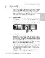
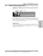
2.1.4
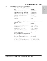
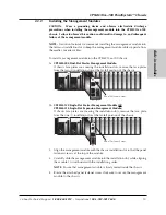
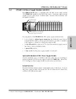
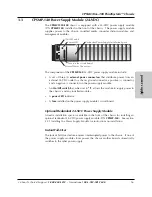
Replacing the Media Converter Slide-in-Modules
CAUTION: Wear a grounding device and observe electrostatic discharge
precautions when replacing the slide-in-module(s). Failure to observe this caution
could result in damage to, and subsequent failure of, the slide-in-module(s).
NOTE:
The media converter slide-in-modules can be hot-swapped.
To replace a media converter slide-in-module:
1. Remove the slide-in-module to be replaced by loosening the panel fastener
screw that secures it to the chassis front. Slide the module from the chassis.
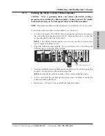
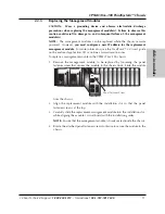
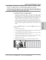
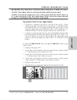
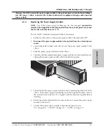
2. Align the replacement slide-in-module with the chassis installation slot so that
the panel fastener screw is at the top.
3. Carefully slide the replacement slide-in-module into the installation slot, while
aligning the module’s circuit board with the installation guides.
NOTE:
Ensure that the slide-in-module is firmly seated inside the chassis.
4. Rotate the attached panel fastener screw clockwise to secure the slide-in-
module to the chassis.
CFMFF100
10BASE-2
CECF100
CFMFF100
0
50½
Link Alert
E
D
CETCF100
CFETF100
CFETF110
CFMFF100
LA
PWR
RXF
RXC
LNK
COL
SPD
PWR
FRX
CRX
FLNK
CLNK
SPD
PWR
FRX
CRX
FLNK
CLNK
10/100TX
RX
TX
10/100SX
100BASE-TX
RX
TX
100BASE-FX
Link Alert
E
D
0
50½
LA
PWR
RXF
RXC
LNK
COL
LKS
PWR
LKM
10BASE-2
10BASE-FL
10BASE-T
LKS
PWR
LKM
LKS
PWR
LKM
Multimode
Singlemode
TX
RX
TX
RX
Multimode
Singlemode
TX
RX
TX
RX
Multimode
Singlemode
TX
RX
TX
RX
I
0
TERM
INIT
RX
TX
LNK
PWR
CPSMM120
SERIAL
10BASE-T
R
E
S
E
T
I
0
CFMFF100
Multimode
Singlemode
TX
RX
TX
RX
LKF
PWR
RXF
RXC
LKC
RX
TX
10BASE-T
10BASE-FL
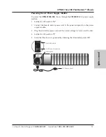
Panel Fastener Screw
Содержание PointSystem CPSMC1300-100
Страница 38: ...38 CPSMC13xx 100 PointSystem Chassis ...


