background image

SAFETY WARNING

Only qualified personnel should install and service the equipment. The installation, starting up, and servicing of heating, ventilating, and air-
conditioning equipment can be hazardous and requires specific knowledge and training. Improperly installed, adjusted or altered equipment 
by an unqualified person could result in death or serious injury. When working on the equipment, observe all precautions in the literature and 
on the tags, stickers, and labels that are attached to the equipment.

Installation, Operation, 
and Maintenance

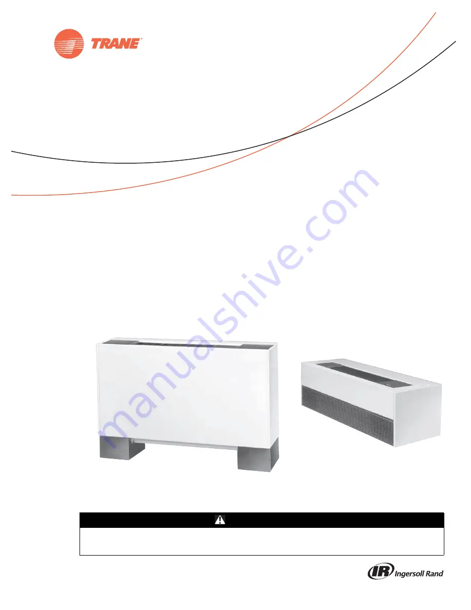
UniTrane™ Fan Coil and Force-Flo™ Cabinet Heater

200 - 1200 CFM
Models FC and FF, Low Vertical Models FCKB and FCLB

UNT-SVX07E-EN

March 2014

Содержание UniTrane Fan Coil

Страница 1: ...ng Improperly installed adjusted or altered equipment by an unqualified person could result in death or serious injury When working on the equipment observe all precautions in the literature and on th...

Страница 2: ...n some states or municipalities may have additional requirements that must also be adhered to for responsible management of refrigerants Know the applicable laws and follow them ATTENTION Warnings Cau...

Страница 3: ...cal Units 43 Fan Coil Horizontal Units 44 Force Flo Vertical Units 45 Force Flo Horizontal and Inverted Units 46 Fresh Air Opening Locations 47 Horizontal Units 47 Vertical Units 48 Wall Box 49 Projec...

Страница 4: ...75 Setting the Address 75 Power Supply 76 Transformer Recommendations 76 Wiring Requirements 77 Connecting Wires 77 Power ON Check 77 Wireless Comm Interface WCI 78 Quantity of WCIs per Network 78 Qu...

Страница 5: ...list 121 Air Filters 121 Coils 122 Steam and Water Coils 122 Coil Winterization 122 Moisture Purge Cycle 123 Cleaning Non Porous Surfaces 123 Cleaning Porous Surfaces 124 Control Device Replacement 12...

Страница 6: ...Activity 143 Overriding Outputs 144 Diagnostics 144 Diagnostics Types 144 Controller Diagnostics 145 Troubleshooting UC400 Controller 146 Fans 146 Valves 147 DX Coils or Electric Heat 147 Outdoor Air...

Страница 7: ...K Exposed fan Model P only L Bottom filter Model P only Digit 13 Fresh Air Damper 0 None A Manual bottom opening B Manual back opening C Manual top opening D Auto 2 position bottom opening E Auto 2 p...

Страница 8: ...re modulating 2 7 Cv 60 psig Q 2 way 3 wire modulating 3 3Cv 60 psig R 3 way 3 wire modulating 3 8 Cv 60 psig X Field supplied NO Y Field supplied NC Z Field supplied 3 wire modulating 1 Field supplie...

Страница 9: ...hout IAQ options 1 Dehumidification 4 Dehumidification with sensor Digit 33 FLA Motor Option 0 Standard FLA ECM mode A Reduced FLA ECM mode Digit 34 0 None Digit 35 Control Function 3 Fan Coil only 0...

Страница 10: ...ting1 with 1 row heating coil Q 2 row cooling heating1 with 2 row heating coil R 3 row cooling heating1 with 1 row heating coil X 2 row cooling only electric heat Note 1Designates coils provided with...

Страница 11: ...r return D Deluxe ball valve supply and return E Deluxe ball valve supply manual circuit setter return Digit 27 Control Type A Fan speed switch D Tracer ZN 010 E Tracer ZN 510 F Tracer ZN 520 H CS T S...

Страница 12: ...s control box assembly These controllers utilize analog signals from a unit mounted control device or from a control device mounted in the occupied space The Customer Supplied Terminal Interface CSTI...

Страница 13: ...or other energy storing components provided by Trane or others refer to the appropriate manufacturer s literature for allowable waiting periods for discharge of capacitors Verify with an appropriate...

Страница 14: ...For proper unit operation the unit must be level zero tolerance in both horizontal axis If the unit is to be ceiling mounted the installer contractor must provide threaded suspension rods All units m...

Страница 15: ...ervice and operating clearances Figure 2 Recommended service clearances for vertical units Model B Vertical Cabinet Model L Low Vertical Cabinet Model A Vertical Concealed Model K Low Vertical Conceal...

Страница 16: ...2 2 3 3 Size Dia x Width in 6 31 x 4 6 31 x 6 5 6 31 x 7 5 6 31 x 6 5 6 31 x 7 5 1 6 31 x 7 5 6 31 x 7 5 Size Dia x Width in 2 6 31 x 6 5 Motor Quantity 1 1 1 1 1 2 2 Filter Data 1 in Throwaway and Pl...

Страница 17: ...C Horizontal Concealed Model D Horizontal Cabinet Model E Horizontal Recessed Model F Wall Hung Cabinet Force Flo units only Model H Vertical Recessed Model J Vertical Slope Top Cabinet Model K Low Ve...

Страница 18: ...onal disconnect switch Auxiliary control box optional 5 1 4 in 6 7 8 in Control box 6 15 16 in A E 6 7 16 in 9 16 in 4 1 2 in 7 in 15 1 2 in 26 1 4 in 1 5 8 in 1 in duct collar 4 5 8 in dia keyslot ha...

Страница 19: ...16 26 5 16 35 13 16 44 5 16 63 5 16 C 22 13 16 27 13 16 37 5 16 45 13 16 64 13 16 D 17 5 16 22 5 16 2 7 13 16 40 5 16 59 5 16 E 19 5 16 24 5 16 33 13 16 42 5 16 61 5 16 Notes Coil connections are alwa...

Страница 20: ...keyslot hanger holes 7 8 in KO Control wiring Front View RH Piping Optional disconnect switch Auxiliary control box optional 5 1 4 in 6 7 8 in Front inlet open or bar grille 4 7 16 in 7 in E A 7 in 8...

Страница 21: ...5 16 35 13 16 44 5 16 63 5 16 C 7 5 8 7 1 8 8 7 8 7 1 8 7 5 8 D 1 16 24 30 42 60 E 19 5 16 24 5 16 33 13 16 42 5 16 61 5 16 F 41 5 16 46 5 16 55 13 16 64 5 16 83 5 16 Notes Coil connections are alway...

Страница 22: ...e and clamp Control box 2 5 8 in bolt holes 3 4 in 3 4 in Front View RH Piping 6 15 16 in B C D 1 11 16 in 1 11 16 in 6 3 8 in Aux box optional 6 1 4 in Control box 1 3 8 in 2 7 8 in 1 3 32 in KO 7 8...

Страница 23: ...13 16 44 5 16 63 5 16 C 22 13 16 27 13 16 37 5 16 45 13 16 64 13 16 D 19 3 8 24 3 8 33 7 8 42 3 8 61 3 8 E 18 1 8 23 1 8 32 5 8 41 1 8 60 1 8 F 19 5 16 24 5 16 33 13 16 42 5 16 61 5 16 Notes Coil conn...

Страница 24: ...ollar optional H B G 6 in G 6 in 3 3 4 in 13 3 4 in 3 3 4 in 1 5 8 in Front outlet quadrifuser or bar grille C D C A 8 in F Optional extended end pocket 2 7 8 in 1 3 8 in Aux box opt 6 1 4 in Control...

Страница 25: ...8 7 1 8 8 7 8 7 1 8 7 5 8 D 18 24 30 42 60 E 17 1 4 22 1 4 19 3 4 40 1 4 40 1 4 F 41 1 4 46 5 16 55 3 16 64 5 16 83 5 16 G 8 5 8 8 1 8 9 7 8 8 1 8 8 5 8 H 16 22 28 40 58 J 19 3 4 23 3 4 31 3 4 39 3 4...

Страница 26: ...8 in bottom access panel Side View Inlet Options 15 5 16 in Front View RH Piping 1 1 2 in 3 4 in 1 11 16 in 3 4 in 2 7 8 in 1 3 8 in Aux box optional 6 1 4 in Control box 8 3 16 in 1 7 16 in 7 8 in KO...

Страница 27: ...37 5 16 45 13 16 64 13 16 D 19 3 8 24 3 8 33 7 8 42 3 8 61 3 8 E 18 1 8 23 1 8 32 5 8 41 1 8 60 1 8 F 32 7 16 37 7 16 46 15 16 55 7 16 74 7 16 G 34 5 16 39 5 16 48 13 16 57 5 16 76 5 16 H 19 3 4 23 3...

Страница 28: ...hanger holes Power wiring bottom only 7 8 in KO 1 3 32 in KO 6 1 4 in 1 3 8 in 2 7 8 in 2 5 8 in bolt holes Side View 10 5 16 in 1 5 8 in 15 1 2 in 26 13 16 in 8 9 16 in Bottom and front inlet and out...

Страница 29: ...1 5 16 26 5 16 35 13 16 44 5 16 63 5 16 C 7 5 8 7 1 8 8 7 8 7 1 8 7 5 8 D 18 24 30 42 60 E 19 5 16 24 5 16 33 13 16 42 5 16 61 5 16 F 19 3 4 23 3 4 31 3 4 39 3 4 59 3 4 Notes Coil connections are alwa...

Страница 30: ...trol wiring Front outlet louvers Control box Optional disconnect switch 7 5 8 in 4 7 16 in 6 15 16 in Front inlet louvers 6 7 16 in A H Wall opening F Front panel J Wall opening 15 1 2 in 7 in G B 4 5...

Страница 31: ...37 5 16 45 13 16 64 13 16 D 17 5 16 22 5 16 31 13 16 40 5 16 59 5 16 E 47 51 63 65 1 2 89 1 2 F 30 30 30 33 1 2 33 1 2 G 2 3 8 2 3 8 2 3 8 4 1 8 4 1 8 H 42 48 57 63 87 J 26 1 2 26 1 2 26 1 2 27 1 2 27...

Страница 32: ...Optional disconnect switch Auxiliary control box optional 5 1 4 in 6 11 16 in Control box Front inlet open or bar grille 4 7 16 in 7 in E A 7 in 8 in F Optional extended end pocket Front View LH Pipi...

Страница 33: ...26 5 16 35 13 16 44 5 16 63 5 16 C 7 5 8 7 1 8 8 7 8 7 1 8 7 5 8 D 18 24 30 42 60 E 19 5 16 24 5 16 33 13 16 42 5 16 61 5 16 F 41 5 16 46 5 16 55 13 16 64 5 16 81 5 16 Notes Coil connections are alwa...

Страница 34: ...1 13 16 in 2 1 3 32 in KOs control wiring bottom only 12 9 16 in 2 11 16 in Front View RH Piping Control box 3 9 16 in 7 1 4 in 13 1 4 in 7 8 in 2 5 8 in dia keyslot hanger holes B 7 8 in Front inlet...

Страница 35: ...16 E 24 1 4 33 3 4 42 1 4 Operating Weight 109 139 147 Shipping Weight 96 123 131 Notes Coil connections are always on the drain pan side and opposite the control box Coil connections are 5 8 in O D...

Страница 36: ...hanger holes Top outlet quadrifuser or bar grille D C C 13 1 2 in 1 15 16 in Air flow Side View 2 5 8 in dia keyslot hanger holes 7 8 in Front View LH Piping Front View RH Piping Unit control top 8 1...

Страница 37: ...4 33 3 4 42 1 4 Operating Weight 125 155 164 Shipping Weight 112 139 148 Notes Coil connections are always on the drain pan side and opposite the control box Coil connections are 5 8 in O D sweat See...

Страница 38: ...ar grille C D C 6 in 7 in 6 in 7 in Front view RH Piping Optional disconnect switch 9 1 4 in Front outlet louvers optional Front inlet louvers Bottom and front inlet and outlet louvers A F 15 1 2 in 2...

Страница 39: ...8 7 8 7 1 8 7 5 8 D 18 24 30 42 60 E 19 5 16 24 5 16 33 13 16 42 5 16 61 5 16 F 19 3 4 23 3 4 31 3 4 39 3 4 59 3 4 Operating Weight 97 125 155 164 218 Shipping Weight 84 112 139 148 200 Notes Coil co...

Страница 40: ...KO 1 3 32 in KO 2 5 16 in 4 9 16 in 3 4 in 1 3 4 in Optional disconnect switch 3 4 in 1 3 4 in 6 5 8 in 5 8 in 9 3 4 in B F Front panel G Wall opening 15 1 2 in 2 1 8 in 4 5 8 in dia keyslot hander h...

Страница 41: ...3 16 D 2 3 8 2 3 8 2 3 8 4 1 8 4 1 8 E 47 51 63 65 1 2 89 1 2 F 30 30 30 33 1 2 33 1 2 G 26 1 2 26 1 2 26 1 2 27 1 2 27 1 2 H 42 48 57 63 87 Operating Weight 78 88 128 139 253 Shipping Weight 68 78 11...

Страница 42: ...ndary drain connection for 3 8 in ID tube Main drain connection for 7 8 in OD copper tube and clamp 1 in duct collar 5 8 in 6 1 8 in 14 1 8 in Back inlet duct collar Filter door used with back duct co...

Страница 43: ...ain pan side and opposite the control box Coil connections are 5 8 in O D sweat See page 43 for locations All duct collar dimensions are to the outside of the collar See page 47 for dimensions for out...

Страница 44: ...l Concealed Horizontal Recessed Recess panel not shown HR HS CR RHS CS RHR 1 in 7 16 in 22 3 8 in CS 21 3 8 in CR 21 1 16 in HR 19 5 16 in HS Dimensions are typical to horizontal unit styles 5 5 16 in...

Страница 45: ...5 5 16 in HS 4 3 8 in HR 5 5 16 in HS 4 3 8 in HR 5 3 8 in HS 4 7 16 in HR 5 5 16 in HS 4 3 8 in HR 23 3 8 in HS 22 3 8 in HR 20 13 16 in HR 21 13 16 in HS HS HR HS HR HS HR HS HR Vertical Concealed V...

Страница 46: ...s and inverted vertical units Horizontal Concealed Horizontal Recessed recess panel not shown 1 in 4 3 8 in HR 5 5 16 in HS 7 16 in 22 3 8 in HS 21 3 8 in HR HR HS Horizontal Cabinet 4 3 8 in HR 5 5 1...

Страница 47: ...1 5 8 in Outside air opening top Keyslot hanger holes 1 5 8 in 2 15 16 in Top View Horizontal Cabinet Horizontal Concealed and Recessed Outside air opening top 3 in 1 in 11 16 in 3 in Side View Outsi...

Страница 48: ...ning bottom 2 15 16 in Keyslot hanger holes 1 5 8 in Vertical Cabinet and Vertical Slope Top Cabinet Front View Side View Vertical Concealed and Recessed Keyslot hanger holes 2 15 16 in 1 5 8 in 3 in...

Страница 49: ...and bottom B A 5 8 in 1 2 in 1 3 8 in 1 8 in Woven aluminum insect screen Clearance for drainage 4 in 1 2 in 3 4 in 1 8 in 1 8 in Continuous mortar ribs top and bottom Table 18 Wall box dimensions inc...

Страница 50: ...t View ISO Rear view ISO Table 19 Projection panel dimensions inches Unit Size 02 03 04 06 08 10 12 A 47 51 63 65 1 2 89 1 2 B 30 30 30 33 1 2 33 1 2 Table 20 Projection panel dimensions inches Unit S...

Страница 51: ...and ceiling openings are properly cut per the unit submittals 5 Verify that installation of horizontal concealed units meets the national Fire Protection Association N F P A Standard 90A or 90Bconcer...

Страница 52: ...down onto the tabs while holding the panel close as possible to the cabinet While the bottom tabs are engaged slide the front panel upward enough to allow the top engaging edge of the front panel to l...

Страница 53: ...s on screws 6 Swing the bottom panel upward into position Hook the safety chain to the bottom panel and the unit Tighten the panel to the unit with the fasteners provided NOTICE Unit Leveling All unit...

Страница 54: ...ral recommendations listed below when installing ductwork for the unit Discharge ductwork should run in a straight line unchanged in size or direction for a minimum equivalent distance of three fan di...

Страница 55: ...Factory Installed Piping Packages This figure shows piping package components and basic arrangement It is not an accurate pictorial of what factory installed piping packages look like Figure 25 Pipin...

Страница 56: ...e 5 8 inch O D 1 2 inch nominal female copper connections The fan coil supply and return piping should not interfere with the auxiliary drain pan or condensate line See Condensate Drain Connections pa...

Страница 57: ...ode based on the supply water temperature On units with a factory piping package the factory straps the changeover sensor to the piping supply water pipe See Figure 28 p 57 and Figure 29 p 57 If the u...

Страница 58: ...o adjustment for the coil to vent However if the coil does not vent immediately unscrew the outer portion of the fitting to expel air from the port If debris has become trapped in the vent completely...

Страница 59: ...the two socket head cap screws and rotate the memory stop around until it touches the back side of the indicator Then tighten the screws to securely set the open memory position The memorystop indica...

Страница 60: ...ensure complete condensate removal b Trane recommends using flat and thermostatic traps because of gravity drain and continuous discharge operation c Use float and thermostatic traps with atmospheric...

Страница 61: ...nsors have an internal thermistor and operate on 24 Vac Options with setpoint knobs are available in Fahrenheit or Celsius See Figure 38 through Figure 47 for available options and model number refere...

Страница 62: ...splay sensor with setpoint adjustment X13511527 01 Wall mounted sensor X13790849 01 Unit mounted sensor X13651467 02 Comm module X13790844 01 Unit mounted zone sensor X13790886 04 Wall mounted wired d...

Страница 63: ...n range for the sensor is as follows Open range 2 500 ft packet error rate 2 percent Usable range 200 ft Typical range 75 ft Height Requirements It is recommended that you mount the back plate a maxim...

Страница 64: ...included hardware 4 To install the zone sensor module to a standard junction box a Level and install a 2 x 4 in junction box installer supplied vertically on the wall b Pull the control wires through...

Страница 65: ...ddress It is not possible to associate more than one sensor to a receiver nor is it possible to associate more than one receiver to a sensor To associate a receiver and sensor the two devices must hav...

Страница 66: ...hannels the clearest channel on which to operate LED1 LED2 and LED3 flash rapidly in succession round robin style while the channel scan is in progress Important Do not attempt association leave the i...

Страница 67: ...every 50 minutes You can manually initiate association see Manual Association page 134 Testing Signal Strength and Battery To verify that the association process was successful and that the batteries...

Страница 68: ...em output will be 2230 see Failure and Default Modes page 135 The receiver conductsan energy scanfor 20 secondsto determine the clearest channel on which to operate LED3 flashes On every 2 seconds whe...

Страница 69: ...7 Section 15 247 Subpart E Digital Modulation Transmission with no SAR FCC Identification TFP 13651127 This device complies with Part 15 of the FCC Rules Operation is subject to the following two cond...

Страница 70: ...s display sensor WDS follow this procedure in the order presented 1 Press the configuration button for three seconds The display will change to configuration mode When the sensor is in configuration m...

Страница 71: ...ons for wireless display sensors Setting Configuration Options Temperature Choose Fahrenheit or Celsius Choose the degree resolution whole degrees half degrees or tenths of degrees Setpoint System Fan...

Страница 72: ...on to try change a locked setting the locked symbol will flash WDS Operating Mode This section describes how to operate the wireless display sensor WDS Figure 64 shows an example of a WDS that has bee...

Страница 73: ...indicates fan speed 3 high 2 medium 1 low The example shown indicates a fan on high speed Not all systems offer all three speeds Indicates that the fan setting is Off Fan Menu Select to request occupa...

Страница 74: ...delines when installing communication wiring on units with a Tracer ZN510 or ZN520 controller Maintain a maximum 5000 ft aggregate run Install all communication wiring in accordance with the NEC and a...

Страница 75: ...nch 3 2 mm flathead screwdriver to set rotary address dials Dials rotate in either direction MAC Address The MAC Address is required by the RS 485 communication protocol on which BACnet operates A UC4...

Страница 76: ...400 controllers ADDRESS 0 1 2 3 4 5 6 7 8 9 x1 0 1 2 3 4 5 6 7 8 9 x10 0 1 2 3 4 5 6 7 8 9 x100 0 0 1 0 2 0 1 ADDRESS 0 1 2 3 4 5 6 7 8 9 x1 0 1 2 3 4 5 6 7 8 9 x10 0 1 2 3 4 5 6 7 8 9 x100 ADDRESS 0...

Страница 77: ...ler is adequately grounded Connecta grounding pigtailat some point along the secondary wire thatrunsbetweenthe controller terminal and the transformer Ground one of the terminals on the controller to...

Страница 78: ...rs Specifications Operating Temperature 40 to 158 F 40 to 70 C Storage temperature 40 to 185 F 40 to 85 C Storage and operating humidity range 5 percent to 95 percent relative humidity RH non condensi...

Страница 79: ...ial When wiring sensors and other input devices to the Tracer controller avoid creating ground loops with grounded conductors external to the unit control circuit Ground loops can affect the measureme...

Страница 80: ...0 22 0 8 0 24 10 0 7 1 2 0 22 0 22 0 5 0 8 0 22 0 22 0 4 0 6 0 24 0 24 12 0 7 1 3 0 22 0 22 0 5 0 9 0 22 0 22 0 4 0 7 0 24 0 24 Table 29 High static ECMs programmed to reduced FLA mode Unit Size 115...

Страница 81: ...90 240 60 3 3 7 50 18 10 480 60 3 4 7 50 9 10 06 208 60 1 2 7 90 38 00 240 60 1 2 10 50 43 80 277 60 1 2 10 50 38 00 208 60 3 3 7 90 21 90 240 60 3 3 10 50 25 30 480 60 3 4 10 50 12 70 Note All data...

Страница 82: ...80 60 3 4 2 5 7 5 9 1 06 208 60 1 2 3 4 7 9 38 0 240 60 1 2 4 5 10 5 43 8 277 60 1 2 4 5 10 5 38 0 208 60 3 3 3 4 7 9 21 9 240 60 3 3 4 5 10 5 25 3 480 60 3 4 4 5 10 5 12 7 08 208 60 1 2 4 5 10 1 48 8...

Страница 83: ...tors and controls including three new circuit modules developed specifically for this series There are four primary components that enable the technology on your product Trane ECM VelociTach motor con...

Страница 84: ...ates various safety and lockout features such as maintaining proper fan speeds if electric heat is called for Status Display The motor control board contains a four digit seven segment display that is...

Страница 85: ...a factory wired transformer A courtesy 10 Vdc supply is provided for use with an external potentiometer or rheostat The 10 Vdc supply supports up to 10 mA draw TB3 right five positions is normally use...

Страница 86: ...heat requests Inputs returns for damper operation requests TB4 left three positions is normally used to control the system with a 0 10 Vdc input from a thermostat controller with a variable speed outp...

Страница 87: ...ion indicated by its model number Under normal and intended operation the only required intervention specific to the new ECM units is the wiring of Wall mounted low voltage fan speed switch inputs to...

Страница 88: ...NG Safety Alert You MUST follow all recommendations below Failure to do so could result in death or serious injury All settings take effect immediately including fan startup and enabling of electric h...

Страница 89: ...dition a Indicates the status being calculated or Fan Motor 1 If off this indicates that either 1 No fan speed is being requested or 2 The fan performance is failing to meet the request refer to ECM M...

Страница 90: ...anged Long Press Hold in Status Display 3 sec Enters the configuration menu Long Press Hold in Configuration Display 3 sec If on a parameter name toggles to the value If on a parameter value saves the...

Страница 91: ...retained Priority Error Display Under special conditions the status display will interrupt briefly to prioritize display of events Notes During error displays the user interface will be disabled unti...

Страница 92: ...monitored Fan Status function if being used will report an inoperative motor Electric heat and changeover heat will be shut down Indicates that Motor 1 has experienced a run away or over speed conditi...

Страница 93: ...output of the controller is significantly greater than the floor setting the first point that the motor will turn on will be above the and value The full range of motor control will not be fully util...

Страница 94: ...ailure to disconnect power and discharge capacitors before servicing could result in death or serious injury Disconnect all electric power including remote disconnects and discharge all motor start ru...

Страница 95: ...f there are fan failures The auxillary heating coil function will continue to operate and respond to the customer heating request parameter should be set to for CSTI units and to for ComfortLink or Ba...

Страница 96: ...t heating or cooling based on customer request but have coil water temperatures that are changed over from heating to cooling or cooling to heating depending on the season and the building equipment a...

Страница 97: ...e if present Electric heat will be locked out where present if hot water is available since SW4 will be factory set to ON in these units SW4 selects the electric heat lockout function where we will lo...

Страница 98: ...Failure to do so could result in death or serious injury All settings take effect immediately including fan startup and enabling of electric heat Caution should be taken to stay clear of hazardous vo...

Страница 99: ...w Spd Mtr 2 Sets the minimum turn on rpm for Motor 2 when the analog input becomes active Op Mode Mtr 1 Sets the operational mode for Motor 1 Must be set to for blower coil units Op Mode Mtr 2 Sets th...

Страница 100: ...ol board triac output based on the thermistor input Operation also depends on and settings Ht Sens Resistor Sets the input impedance of the thermistor input Should be pre set to OUT for Tracer ZN cont...

Страница 101: ...fan speeds For a size 1000 or 1200 unit using typical unit operating fan speeds Note The indicator is unit specific and may indicate Off at this point refer to thermistor function for more informatio...

Страница 102: ...e open Remove all foreign material from the drain pan and check the pan opening and condensate line for obstructions For steam coils slowly turn the steam on full for at least 10 minutes before openin...

Страница 103: ...esh air damper cycle with control valve option to maintain setpoint temperature In cooling mode the fan cycles from off to medium and in heating mode it cycles from off to low When no heating or cooli...

Страница 104: ...board Unit mounted zone sensors use a sensor placed in the unit s return air stream Each zone sensor is equipped with a thumb wheel for setpoint adjustment Fan Mode Switch The zone sensor may be equi...

Страница 105: ...d on the unit For example cooling operation is requested and cold water 5 lower than room temperature flows into the unit Select the correct temperature setpoint Note Select and enable zone sensor tem...

Страница 106: ...heating capacity Occupied Standby Mode The controller can be placed into the occupied standby mode when a communicated occupancy request is combined with the local hard wired occupancy binary input s...

Страница 107: ...more information about abnormal fan operation The controller operates the supply fan continuously when the controller is in the occupied and occupied standby modes for either heating or cooling The c...

Страница 108: ...speed increases as the space temperature rises above the active cooling setpoint Additional flexibility built into the controller allows you to enable or disable the local fan switch input The fan mod...

Страница 109: ...r the desired heating or cooling If the water temperature is not usable for the desired mode the controller continues to compare the entering water temperature against the effective space temperature...

Страница 110: ...pen closed is set at the factory See Table 54 However you can configure each of the four binary inputs as normally open or normally closed The controller will be set properly for each factory supplied...

Страница 111: ...the electric heat stage For those 2 pipe changeover units electric heat will not be energized while the hydronic supply is hot 5 or more above the space temperature J1 6 Cool valve close Note 1 J1 9 H...

Страница 112: ...ne the controller s active setpoint When a building automation system or other controller communicates a setpoint to the controller the controller ignores the hard wired setpoint input and uses the co...

Страница 113: ...ily pressing the on button during unoccupied mode places the controller in occupied bypass mode for 120 minutes You can adjust the number of minutes in the unit controller configuration using Rover se...

Страница 114: ...be checked to determine if the status of the point s is acceptable to allow equipment operation Random Start Random start is intended to prevent all units in a building from energizing at the same ti...

Страница 115: ...starts the occupied bypass timer without changing to occupied bypass mode If the controller is placed in unoccupied mode before the occupied bypass timer expires the controller is placed into occupied...

Страница 116: ...temperature value If the entering water temperature value is less than 5 F 2 8 C above a valid zone temperature value for hydronic heating and greater than 5 F 2 8 C below a valid zone temperature val...

Страница 117: ...ature and flow setpoints will revert to default values The exhaust function is coordinated with the supply fan and outdoor return air dampers as follows The exhaust fan energizes when the fan is runni...

Страница 118: ...omizing and moves the outdoor air damper back to its predetermined minimum position based on the current occupancy mode or communicated minimum outdoor air damper position If an outdoor air temperatur...

Страница 119: ...ow limit Smart Reset The controller will automatically restart a unit that is locked out as a result of a Low Coil Temp Detection BI3 diagnostic Referred to as smart reset this automatic restart will...

Страница 120: ...Binary Status page or by using the reset button on the Alarms page in Tracer TU Freeze Avoidance Freeze avoidance is used for low ambient temperature protection It is initiated only when the fan is O...

Страница 121: ...serious injury Maintenance Checklist Table 61 Maintenance Checklist Frequency Maintenance Every week Observe unit weekly for any change in running condition and unusual noise Every month Clean or rep...

Страница 122: ...il and the drain pan with cool clean water 8 Repeat steps 6 and 7 as necessary 9 Straighten any coil fins that may have been damaged during the cleaning process 10 Confirm the drain line is open follo...

Страница 123: ...s Turns off the cooling coil Opens any variable air volume terminals connected to the air handler Operates the supply fan for 10 to 15 minutes Air movement discourages water condensation and hastens r...

Страница 124: ...ain pan on a horizontal unit 1 Peel the insulation from the edges of the pan s underside to access the mounting screws see Figure 93 2 Remove the screws and lower the end of the drain pan closest to t...

Страница 125: ...aminated area s with a mild bleach and water solution or an EPA approved sanitizer specifically designed for HVAC use 6 Immediately rinse the affected surfaces thoroughly with fresh water and a fresh...

Страница 126: ...e two fan board mounting screws 4 Slide the fan board out horizontally to remove Horizontal Units 1 Open the bottom panel of cabinet and recessed models 2 Remove the main drain pan following the instr...

Страница 127: ...ost of the wiring Please be sure to remove or secure the wiring before removing fan board Fan board attachment screws are located on the front left and right edges of fan boards and may be concealed b...

Страница 128: ...her if a double shafted motor 6 Unscrew the motor and remove 7 Insert the replacement motor plug must face front of fan board and drive the screws in with 100 in lb of torque Figure 100 Motor attachme...

Страница 129: ...s not removed Remove shipping spacers and or bolts Motor runs and then dies down Partial loss of line voltage Check for loose connections Determine adequacy of main power supply Motor does not come up...

Страница 130: ...faces Excess dirt in unit Missing filters Replace filters Filter bypass Reduce filter bypass by ensuring all blockoffs are in place Microbial growth mold inside air handler Standing water in drain pan...

Страница 131: ...twork Association with a device has been manually removed LED1 Off LED2 Off LED3 2 blink pattern repeated continuously1 Address set to 000 Address not set to between 001 999 LED1 Off LED2 Off LED3 3 b...

Страница 132: ...n LED1 Off LED2 On LED3 On Displays for 5 seconds then constantly Off Satisfactory signal strength Adequate signal strength for reliable communication Moving sensor or receiver may improve signal stre...

Страница 133: ...ensor ships with Energizer L91 batteries already installed Replacement batteries are available at Trane Service Parts Centers p n X13770035010 or other local suppliers Battery Life Battery life is fiv...

Страница 134: ...or proper functioning Disassociation The receiver disassociates from the sensor by removing all stored association information conducts a channel scan and restarts itself if any of the following are t...

Страница 135: ...ing Output Resistance 4 When the testis complete reset the receiver address to its previous setting 5 Press the Test button on the sensor to force re association 6 Confirm association and communicatio...

Страница 136: ...ide or settings change LED Activity Green Status LED The green LED normally indicates whether the controller is powered on 24 Vac supplied Refer to Table 73 Table 71 Receiver resistance table for all...

Страница 137: ...Manual Output Test Procedure Follow the procedure below to test Tracer ZN010 ZN510 and ZN520 controllers 1 Press and hold the TEST button for at least two seconds not exceeding 5 seconds and then rele...

Страница 138: ...the controller attempts to clear all diagnostics 3The fresh air damper BOP6 only energizes during this step if binary output 6 has been configured as a fresh air damper 4After the Fresh Air Damper st...

Страница 139: ...predefined sequence The first and last outputs of the sequence reset the controller diagnostics See page 137 for more information about the manual output test Cycling Power When someone turns off the...

Страница 140: ...ir temp failure Off Valves Closed Fresh air damper Closed Electric heat Off Baseboard heat Off Fresh air temp failure On Valves Enabled Fresh air damper Minimum position3 Electric heat Enabled Baseboa...

Страница 141: ...es not match the actual end devices the valves may not work correctly Manual output test The controller includes a manual output test sequence to verify binary output operation and the associated wiri...

Страница 142: ...ssociated output wiring However based on the current step in the test sequence the electric heat may not be on Refer to Manual Output Test page 137 Diagnostic present A specific list of diagnostics af...

Страница 143: ...does not operate For the controller to operate normally a 24 Vac input voltage must be applied When the green LED is off continuously the controller does not have sufficient power or has failed Unit...

Страница 144: ...ler or if it is capable of talking to the controller Also determine if the communication status shows down all of the time In addition check polarity and baud rate For more information refer to Instal...

Страница 145: ...Note The generic binary output is unaffected by diagnostics Table 87 Diagnostics generated by UC4000 controller Diagnostic Probable Cause Consequences Diagnostic Type Filter change required Fan run ho...

Страница 146: ...n unoccupied mode the fan cycles between OFF and the highest fan speed No power to the controller If the controller does not have power the unit fan does not operate For the controller to operate norm...

Страница 147: ...configuration The controller must be properly configured based on the actual installed end devices and application If the unit configuration does not match the actual end device the valves may not wo...

Страница 148: ...per is open during occupied mode when the fan is running and closed during unoccupied mode Unit configuration The controller must be properly configured based on the actual installed end devices and a...

Страница 149: ...access lid should be used to verify engine configuration settings For proper operation of the system all plugs must be firmly seated in all boards and motors Insecure connections will cause malfunctio...

Страница 150: ...se floor parameter that can be configured to reject signals below the noise floor The noise floor parameter is set too high it can be lowered as long as there are acceptable noise levels on the inputs...

Страница 151: ...commissioning the unit The board is pre configured with safe values but will NOT work correctly unless properly configured Only genuine Trane replacement components with identical Trane part numbers s...

Страница 152: ...ached to the CSTI or standard adapter boards please ensure that the green wire is attached to the engine board white connector as shown in Figure 106 4 Ensure that the new VelociTach motor board contr...

Страница 153: ...target for a specific period of time the unit will disable electric heat and fan status indicators MCA MOP and Power Draw ECM motors have variable output but are shipped at specific settings to delive...

Страница 154: ...h ground Grn Splice Legend Device Designation Adapter Board ECM Engine Description Line Number 28 44 1U2 1U3 1T1 1S1 Transformer Disconnect Switch 25 3 481 Fan Motor 24 J Jack Cap Connector P Plug con...

Страница 155: ...ber 28 44 1U2 1U3 Fan Motor J Jack Cap Connector P Plug connector Device Prefix Location Code Area Location Control Panel Control End Piping End Fan Section Coil Section Customer Installed Field Suppl...

Страница 156: ...tion Line Number 28 44 1U2 1U3 1T1 Transformer 25 Fan Motor 24 J Jack Cap Connector P Plug connector Device Prefix Location Code Area Location Control Panel Control End Piping End Fan Section Coil Sec...

Страница 157: ...Wiring Diagrams UNT SVX07E EN 157 Table 99 Typical wiring diagram for Tracer ZN520 unit with four pipe configuration condensate overflow switch and wall mounted zone sensor...

Страница 158: ...gine Description Line Number 28 44 1U2 1U3 1T1 Transformer 25 Fan Motor J Jack Cap Connector P Plug connector Device Prefix Location Code Area Location Control Panel Control End Piping End Fan Section...

Страница 159: ...Wiring Diagrams UNT SVX07E EN 159 Table 101 Typical wiring for UC400 controller with WCI...

Страница 160: ...vanced controls and HVAC systems comprehensive building services and parts For more information visit www Trane com Trane has a policy of continuous product and product data improvement and reserves t...

Отзывы: