


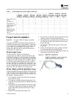


Figure 3.
Typical UCP2 before retrofit
Installation
CVRF-SVN005C-EN
13
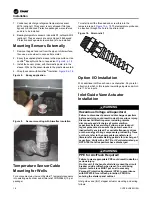
Removal of Existing Panel
Remove the existing UCP2 panel. The existing brackets on the
chiller will be reused to mount the new control panel.
Installation of New Control Panel
Install the new control panel using existing hardware to mount
it to the UCP2 brackets.
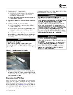
Wiring Installation
WARNING
Proper Field Wiring and Grounding
Required!
Failure to follow code could result in death or serious
injury.
All field wiring MUST be performed by qualified
personnel. Improperly installed and grounded field
wiring poses FIRE and ELECTROCUTION hazards. To
avoid these hazards, you MUST follow requirements for
field wiring installation and grounding as described in
NEC and your local/state/national electrical codes.
Unless otherwise indicated, all 115 volt control circuits use, as
a minimum, #16 AWG, 600 volt wire. Be sure to use existing
conduit wherever possible and separate all 115V wiring from
any low voltage circuits.
Most wiring will use the existing wires removed and marked
from the original panel and moved to the terminal block in the
new panel. Some wires may need to be connected directly on
a LLID terminal.
details the “before and after” of wires from the original panel to
the new panel. Also refer to the connection and schematic
diagrams listed in
“Wiring Diagram Matrix,” p. 46
for additional
detail.
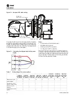
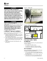
For 50 Hz applications, the control power transformer (1T1) is
supplied as a 60 Hz application. To convert from 60 Hz to 50
Hz, the following step must be performed: move wire 2H from
H3 on 1T1 to H2.
If you have wired a temporary thermostat and 115 Vac power
source to the oil heater leads, wait to connect these wires until
the Tracer® AdaptiView™ retrofit is complete to avoid too
much cooling of the oil.
The information in
describes where the wiring
that exited the old control panel is to be rewired in the new
factory panel. Also refer to the connection and schematic
diagrams listed in
“Wiring Diagram Matrix,” p. 46
.
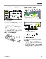
Stepper Module
(1U3)
Circuit Module (1U2)
Chiller Module (1U1)
Option Module
(1U5) (Optional)
Digit 6
Table 6.
Field wiring cross reference, UCP2 to new
panel
Existing
Wire #
From
(in Existing Panel)
To
(in New
Panel)
Description or
Comments
P5A
1U1 J3-1
1A13 J2-1
External Auto/Stop
P5A
1U1 J3-2
1A13 J2-2
External Auto/Stop
P5B
1U1 J5-3
1A13 J2-3
Emergency stop
P5B
1U1 J5-4
1A13 J2-4
Emergency stop
Black
1U2 J3-1
1A26 J2-1
Motor winding temp
sensor
White
1U2 J3-3
1A26 J2-2
Motor winding temp
sensor
Green
1U2 J3-5
1A26 J2-3
Motor winding temp
sensor
Red
1U2 J3-6
1A26 J2-4
Motor winding temp
sensor
1U1 J14-1
1A5 J2-1
Condenser water pump
relay 5K2 coil
5K2 Neutral
Open neutral
Condenser water pump
relay 5K2 neutral
1U1 J12-1
1A5 J2-4
Evap water pump relay
5K1 Neutral
Open neutral
Evap water pump relay
neutral
42A
1U2 J20-1
1X1-22
Oil Heater 4HR1
2N
1TB1-4
1X1-8
Oil Heater 4HR1 Neutral
2M
4B3-2
1X1-7
Oil pump motor (4B3)
neutral
9B/19A
1U2 J22-1
1X1-16
to 4K8 oil pump relay
1TB1-10
1X1-4
to 5K1, 5S2 flow switches
1TB1-11
1X1-4
to 5K2, 5S3 flow switches
1TB1-12
1X1-19
from 5K1, 5S2 flow
switches
1TB1-13
1X1-20
from 5K2, 5S3 flow
switches
Starter Panel Ground 1X1-G
Panel ground (from
starter)
2TB1-1 (1TB1-1)
1X1-1
120 Vac power to control
panel from starter 2TB1-
1
2TB1-2 (1TB1-2)
1X1-6
120 Vac neutral to control
panel from starter 2TB1-
2
Содержание Symbio CVRF
Страница 43: ...Figure 57 Dual CT wiring example Starter Work CVRF SVN005C EN 43...
Страница 47: ...Notes CVRF SVN005C EN 47...


