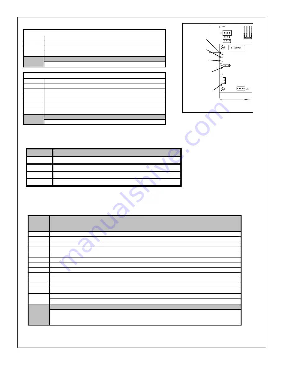
TAM818
EVC FAULT CODES (RED LED)
EVC STATUS CODES (GREEN LED)
EVC UNIT LED (BLUE LED)
EVC STATUS LED (Non Heat Pump Systems)
Flash
1
Cool mode selected / No active call
2
Active call for 1st stage cooling
3
Active call for 2nd stage cooling
(1)
(1) Single stage OD systems will report 2nd stage flash codes
EVC STATUS LED (Heat Pump Systems)
Flash
1
Cool mode selected / No active call
2
Active call for 1st stage cooling or defrost
3
Active call for 2nd stage cooling or defrost (1)
4
Heat mode selected or Thermostat system switch off
5
Active call for 1st stage heating
6
Active call for 2nd stage heating (1)
(1) Single stage OD systems will report 2nd stage flash codes
NOTE:
NOTE:
Unit LED
1
Flash
Rapid
Off
SOLID
ON
Description
Normal
(1
flash
every
4
seconds)
Communication
Busy
Error
(2
flashes
per
second)
No
Power
Communications
cannot
be
established
with
the
AFC
EVC
SW1
R410A / R22
TEST
CLOSE
OPEN
J4
OPEN
TEST
CLOSE
STATUS
LED
FAULT
LED
UNIT
LED
J11
FAULT
UNIT
STATUS
EVC
Fault LED
Description
OFF
Standby
1
Stepper Motor or wiring harness has an open circuit or intermittent short
2
Control has detected an internal failure (Verify EEV motor resistance and harness wiring)
3
Saturated Gas Sensor input out of range (Verify resistance, 5VDC output from control)
(1)
4
Evaporator Gas Sensor input out of range (Verify resistance, 5VDC output from control)
(1)
5
Stepper Motor Coil is shorted
(2)
6
Valve is not responding to a change in position. (Possible stuck valve)
7
High superheat (Low charge or restriction)
10
Low superheat (Check airflow, possible stuck valve)
(3)
11
Condensate drain switch activated for 100 seconds (Check condensate switch and drain)
(2)
13
Indoor frost protection activated (Check refrigerant charge and airflow)
(2)
14
Internal communication fault (All operation is terminated) (Cycle power & check wire terminations)
15
Configuration fault (All operation is terminated) (Cycle power & check if PM error is present)
16
Outdoor status fault (All operation is terminated)
1) EEV will try to go to a safe position, cooling attempt allowed
2) K1 relay opens on EVC, Yo disabled
3) Cooling attempt allowed, 5 consecutive Y calls with same condition disables Yo
NOTES:
Содержание Hyperion AAM8A0A24V21CA
Страница 3: ...TAM8 3 WIRING DIAGRAM FOR AM8 AIR HANDLERS 5 ET WIRING MAY BE BROWN OR ORANGE...
Страница 35: ...TAM8 35...


