background image


Page 16 


i. Precaution for very low outdoor temperatures 

In case of installation conditions with a very low temperature:  


If there is a storage on board the unit, insert electric resistances to be calculated by: 

PrWatt = V x (10 – tmin) / 860 

where: PrWatt is the resistance power (Watt) and tmin is the lower temperature (°C)


If there is no storage, maintain the water temperature higher than 10°C by inserting thermostatic resistance with 

power calculated as in case 1. 


c. 

ANTIFREEZE PROTECTION ON THE HEAT EXCHANGER 

Two or more protection methods should be foreseen when designing the system as a whole: 
1. Continuous water flow circulation inside piping and exchanger when ambient air temperature is holding below 5 °C. 

This implies what follows: 

-  if the water flow inside piping and exchanger of the unit is due to an external pump installed by the customer, the 

on/off command of this pump must always be the one provided by the unit controller through the relevant free 

potential contact in the electrical cabinet. 

-  as long as the ambient air temperature is holding below 5 °C the unit must always be electrically supplied. 

Moreover the customer pump, if present, must always be electrically supplied alike and functioning properly. 

2. Addition of an appropriate amount of glycol inside the water circuit. 
3. Additional heat insulation and sufficient heating of exposed piping. 

 
IMPORTANT: Trane can provide various optional kits (they are not included in the Low ambient kit down to -

10°C) for the protection of all the components of the hydraulic circuit inside the unit (pumps, pipes and tank). 

For selection and price; contact your local Trane office.


4. Emptying and cleaning of the heat exchanger during the winter season. 

It is the responsibility of the installer and/or of local maintenance personnel to ensure two or more of the described antifreeze 

methods. Continuously verify, through routine checks, that appropriate anti-freeze protection is maintained. 

Failure to follow the instructions above could result in damage to some of the unit’s components. Damage from freezing is 

not covered by the warranty. 

CAUTION

: The unit water pipes are not protected against the risk of water freeze-up when the unit is not electrically 

powered and when the power and control of the external water pumps is not managed by the unit controller. The owner or 

local maintenance personnel must provide appropriate solutions to prevent freezing. 


Содержание FLEX HP HT

Страница 1: ...ntenance July 2022 CG SVX059A GB Original instructions FLEX HP HT Air cooled heat pump with vapour injection scroll compressors R410A refrigerant For hot water production up to 65 C Cooling capacity 50 144 kW Heating capacity 54 154 kW ...

Страница 2: ...Page 2 ...

Страница 3: ......

Страница 4: ... 12 7 HYDRAULIC VERSIONS 17 8 PUMPS CHARACTERISTICS 20 9 ELECTRICAL PANEL AND ELECTRICAL DATA 23 10 OPERATOR RESPONSABILITIES 26 11 START UP PRELIMINARY PROCEDURES 26 12 CHECK LIST MANDATORY OPERATION CONTROL BEFORE START UP 27 13 START UP 32 14 MAINTENANCE 34 15 ORDINARY MAINTENANCE 38 16 RECOMMENDED SPARE PARTS 39 17 TROUBLESHOOTING 40 ...

Страница 5: ...ed out by a Trane authorised assistance centre The warranty is subject to regular maintenance of the unit which is appropriately indicated in the machine log book located inside the electrical panel The warranty is automatically over in case of payments not fulfilled non performance of the contract and even if the units show tampering without TRANE writing approvals Non observance of the above men...

Страница 6: ...onsibility for damage to things and unauthorized personnel in case of absence of clear and static limiting systems of the risk areas and of the relevant warning and danger signs c GENERAL PRECAUTIONS The operator must only intervene on the unit commands he or she must not open any panels except for the one which gives access to the control module The installer must only intervene on the connection...

Страница 7: ...ving certified that it is correctly connected to the plant inform the technician promptly of any alarms which appear on the unit do not reset the alarms to manual restart without having first identified the cause and removed it f PREVENTION AGAINST RESIDUAL MECHANICAL RISKS install the unit in accordance with the provisions of the following manual carry out all the maintenance operations provided ...

Страница 8: ...ed technicians may carry out maintenance operations Before carrying out any maintenance the following must beperformed isolate the unit from the mains electricity by using the external knife switch place a notice on the external knife switch which says do not use maintenance in progress make sure that any possible on off commands are disabled use appropriate safety equipment helmet isolating glove...

Страница 9: ...ssure switch PA Due to the fact that no Schrader valve is installed in the pressure port the dedicated high pressure switch is plugged into it is absolutely forbidden to pull out the high pressure switch PA if the unit is not completely void of refrigerant Failure to follow these instructions could result in death or serious injury Part of the refrigerant circuit drawing which includes the high pr...

Страница 10: ...ectronic components b OPERATING LIMITS Unit operation is permitted within the limits indicated in the diagram provided in 3 3 CAUTION The operation outside the limits specified may cause the activation of the protections and disrupt the operation of the unit and in extreme cases damage the unit In case of doubt consult the factory These operating limits apply to unit operating at full load c OPERA...

Страница 11: ...hstand the weight of the unit while running To reduce the transmission of vibrations to the supporting structures fit shock absorbers in every fastening point Rubber shock absorbers are recommended for units installed on the ground spring shock absorbers for units installed on roofs Open spaces around the unit must be provided to allow for the passage of necessary airflow and to allow maintenance ...

Страница 12: ...ind of chimneys smokestacks and different effluent discharges f PRECAUTIONS AGAINST THE PRESENCE OF FOLIAGE AND FOREIGN BODIES Avoid installing the unit in the immediate vicinity of plants that can prevent proper intake and discharge air g CONTROL OF COMPRESSOR FASTENING The compressors are fitted on shock absorbers For fixing through spring anti vibration mounts it is necessary to remove blockage...

Страница 13: ...he unit functions with a unit voltage imbalance between the phases of above 2 the warranty is invalid c UNIT VOLTAGE PHASING It is important that proper rotation of the compressors be established before the unit is started Proper motor rotation requires confirmation of the electrical phase sequence of the power supply The motor is internally connected for clockwise rotation with the incoming power...

Страница 14: ...gular tests and proper chemical treatment of water are recommended before starting up the new unit In the event that glycol is added to the hydraulic system as anti freeze protection pay attention to the fact that intake pressure will be lower the unit s performance will be lower and water pressure drops will be greater All unit protection methods such as anti freeze and low pressure protection wi...

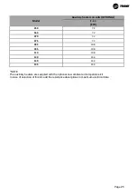
Страница 15: ... 0 21 2 2 1 85 2 9 1 24 1 085 0 7 41 1 9 1 24 2 2 4 36 1 10 6 28 3 095 0 8 35 2 10 1 27 0 2 7 30 8 11 9 31 6 110 0 9 26 1 11 8 31 5 3 2 23 1 13 8 36 8 130 1 1 18 9 14 0 37 3 3 7 16 8 16 3 43 4 140 1 2 18 3 14 7 39 3 3 9 16 3 17 2 45 9 145 1 2 16 9 15 4 41 2 4 1 15 0 18 1 48 2 KEY V recommended water content of the plant with dT 5 C on the heat exchanger Q min minimum water flow to the heat exchang...

Страница 16: ... 095 0 8 35 2 9 9 26 3 2 7 30 8 11 7 31 2 110 0 9 26 1 11 5 30 7 3 1 23 1 13 5 36 0 130 1 1 18 9 13 7 36 5 3 6 16 8 15 8 42 0 140 1 2 18 3 14 4 38 4 3 8 16 3 16 7 44 4 145 1 2 16 9 15 1 40 3 4 0 15 0 17 5 46 6 KEY V recommended water content of the plant with dT 5 C on the heat exchanger Q min minimum water flow to the heat exchanger Q max maximum water flow to the heat exchanger dpw K Q 1000 Q 0 ...

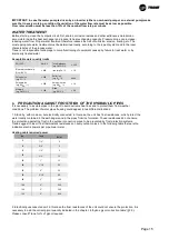
Страница 17: ...g S2 l None Sulphate ion mg SO24 l 200 Ammonium ion mg NH4 l 1 0 Alkalinity mg CaCO3 l 100 Silica mg SiO2 l 50 b PRECAUTION AGAINST FROST RISK OF THE HYDRAULIC PIPES It is necessary to insulate pipes in the plant to avoid extreme heat loss and to protect them from weather conditions The problem of water pipes freezing could appear in two different situations 1 Stand by with mode on but electricall...

Страница 18: ...plied Moreover the customer pump if present must always be electrically supplied alike and functioning properly 2 Addition of an appropriate amount of glycol inside the water circuit 3 Additional heat insulation and sufficient heating of exposed piping IMPORTANT Trane can provide various optional kits they are not included in the Low ambient kit down to 10 C for the protection of all the component...

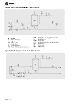
Страница 19: ...ater circuit user side to keep the warranty No water flow control device is installed on the unit so the flow switch is always provided as a loose accessory optional and must be installed by the customer i Hydraulic diagrams HYDRAULIC SCHEME WITH HYDRAULIC VERSION AND WATER TANK FROM SIZE 050 TO 145 Hydronic kit with 1 pump 1 2 3 Versions Hydronic kit with 2 pumps 4 5 6 Versions M Gauges S Water d...

Страница 20: ...tank D E F Versions M Gauges S Water discharge P Pump SV Safety valve SF Relief valve ET Expansion valve PD Water differential pressure switch PRS Empty plant security pressure switch R Shut off valve EWR Evaporator PR Additional pump water pressure switch VR Check valve WT Water tank GR Filling group ...

Страница 21: ...can be horizontal and vertical screw in thread RP 1 ISO7 1 It should be installed far from elbows or throttling with an arrow on flow direction If pipe is vertical recalibrate range to balance paddle weight If the device is downwards mounted take care to slags and apply it in a straight pipe far from filters valves etc with length at least 5 times the diameter of pipe upstream and downstream the u...

Страница 22: ...re drop kPa F L I Full load electrical power F L A Full load operating current Hp Head pressure pump Hu Available pressure Model Pt qw dpw Ref Curve Expansion vessel FLI FLA Hp Hu kW m3 h kPa l kW A kPa kPa 050 58 8 10 3 15 6 Pump 3 5 1 1 3 2 210 194 060 66 5 11 6 17 6 Pump 3 5 1 1 3 2 198 180 070 76 3 13 4 17 7 Pump 4 12 1 76 3 2 195 177 075 84 2 14 7 18 5 Pump 4 12 1 76 3 2 185 167 085 98 8 17 3...

Страница 23: ...ssure drop kPa F L I Full load electrical power F L A Full load operating current Hp Head pressure pump Hu Available pressure Model Pt qw dpw Ref Curve Expanion vessell FLI FLA Hp Hu kW m3 h kPa l kW A kPa kPa 050 58 8 10 15 6 Pump 6 5 3 8 6 6 295 0 279 060 66 5 12 17 6 Pump 6 5 3 8 6 6 290 0 272 070 76 3 13 17 7 Pump 6 12 3 8 6 6 287 0 269 075 84 2 15 18 5 Pump 6 12 3 8 6 6 280 0 262 085 98 8 17 ...

Страница 24: ...sure drop kPa F L I Full load electrical power F L A Full load operating current Hp Head pressure pump Hu Available pressure Model Pt qw dpw Ref Curve Expansion vessel FLI FLA Hp Hu kW m3 h kPa l kW A kPa kPa 050 58 8 10 3 15 6 Pump 8 5 6 6 11 5 472 456 060 66 5 11 6 17 6 Pump 8 5 6 6 11 5 470 452 070 76 3 13 4 17 7 Pump 9 12 6 6 11 5 560 542 075 84 2 14 7 18 5 Pump 9 12 6 6 11 5 555 537 085 98 8 ...

Страница 25: ...ts Connect the terminals as per the wiring diagram on the unit terminal X a visual or audible alarm or any external supervision system BMS to monitor its operation is allowed See the wiring diagram of the unit for wiring WARNING To avoid corrosion overheating or general damage at terminal connections unit is designed for copper conductors only In case of aluminum conductors an intermediate connect...

Страница 26: ...5 1 147 4 5 9 41 7 74 1 204 8 68 5 121 238 130 41 5 72 6 158 6 12 47 5 84 6 224 5 78 0 138 263 140 44 6 78 1 158 6 12 50 6 90 1 228 5 81 4 144 269 145 47 9 83 8 197 6 12 53 9 95 8 271 9 87 8 155 2 313 6 Electrical data referred to 400V 3PH N 50Hz Maximum operating admitted conditions 10 Maximum phase unbalance 3 F L I Full load electrical power F L A Full load operating current L R A Compressor mo...

Страница 27: ... 7 2 060 7 2 070 7 2 075 7 2 085 10 8 095 10 8 110 10 8 130 14 4 140 14 4 145 14 4 NOTE The auxiliary heaters are supplied with the optional Low ambient air temperature kit In case of selection of this kit add the resistance absorptions to maximum electrical data ...

Страница 28: ...he water pump of the evaporator with the calibration valve shut and then slowly open it Discharge the air from the high points of the water circuit and check the direction of the water flow Carry out calibration of the flow by using a measurer if present or available or by means of a combination of the readings of the manometers and the thermometers In the starting phase calibrate the valve on the...

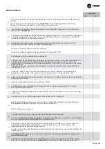
Страница 29: ...FECTS OR DAMAGES RESULTING FROM MODIFICATIONS OR CHANGES UNIT TAMPERING UNAUTHORIZED MODIFICATIONS TO THE REFRIGERANT CIRCUIT OR THE HYDRAULIC CIRCUIT OR THE ELECTRICAL PANEL OR CHANGES TO THE UNIT OPERATING PARAMETERS MADE BY A THIRD PERSON WITHOUT A WRITTEN AUTHORIZATION ISSUED BY TRANE THE UNIT SHALL BE CONFORM TO TRANE WIRING DIAGRAMS AND TECHNICAL DOCUMENTATION IN CASE OF RELEVANT DIFFERENCE ...

Страница 30: ...R OR ANY ADDITIONAL CONTROLLER HAS BEEN INSTALLED 18 THE CONNECTION WIRES ARE SHIELDED 19 REMOTE CONTROL DEVICES OR INTERFACES ARE CONNECTED TO THE ELECTRICAL PANEL IN CONFORMITY WITH TRANE WIRING DIAGRAMS 20 ELECTRONIC DEVICES ARE INTACT AND DON T DISPLAY ANY DAMAGE 21 AN EXTERNAL WATER PUMP IS ELECTRICALLY CONNECTED TO THE ELECTRICAL PANEL IN ACCORDANCE WITH THE WIRING DIAGRAMS PROVIDED BY TRANE...

Страница 31: ...LATE AND DIMENSIONAL DRAWINGS HOT WATER INLET HOT WATER OUTLET COLD WATER INLET COLD WATER OUTLET ETC 34 RUBBER JOINTS ARE INSTALLED ON THE HYDRAULIC CONNECTIONS IN ORDER TO MINIMIZE VIBRATIONS BETWEEN THE UNIT AND WATER PIPES 35 SHUTOFF VALVES ARE INSTALLED ON THE HYDRAULIC CIRCUIT 36 THE EXPANSION TANK IS INSTALLED ON THE HYDRAULIC CIRCUIT EXPANSION TANK CAPACITY CONCURS WITH THE WATER PLANT CAP...

Страница 32: ...AL VOLTAGES THAT CAN CAUSE DANGEROUS CORROSIONS 45 THE EVAPORATOR WATER FLOW IS COMPLIANT TO THE DOCUMENTATION PROVIDED BY TRANE 46 THE WATER PUMPS ARE CORRECTLY SET UP IN ACCORDANCE WITH THE PLANT WATER FLOW AVAILABLE HEAD PRESSURE AND PRESSURE DROP 47 THE PUMP IMPELLERS ARE MECHANICALLY UNBLOCKED AND UNCLOGGED FREE FROM ANY CONSTRAINTS DATE AUTHORIZED SERVICE NAME AND SIGNATURE CUSTOMER NAME AND...

Страница 33: ...ay mean an excess of charge After intervention on the charge it is appropriate to check that the unit runs within the declared values with unit steadily running on a full charge measure the temperature of the suction line downstream of the thermostatic valve bulb read the balance pressure to the evaporator on the low pressure manometer and the corresponding saturation temperature Overheating is eq...

Страница 34: ... at the end IMPORTANT If the unit has not been provided with integrated pump on board do not turn off the external pump before 3 minutes have elapsed after turning off the last compressor The early shutdown of the pump causes a water flow alarm failure 13 START UP PRELIMINARY CONTROLS Before starting up the equipment it is very important to check that all the operations described in the paragraph ...

Страница 35: ...erant as in the indications above Restart the compressor Run for 20 minutes at full load and check the oil level The units use POE oil In case of burns for the electrical motor or fault of the compressor it is necessary to make a test to check the acidity of the lubricant oil and eventually clean the circuit to reduce the acidity to correct values mounting for instance an antiacid filter and chang...

Страница 36: ...mparison by reading the corresponding values directly on the display of the microprocessor on board Totemporarily turn off the unit put on standby the unit key or open the remote contact terminals shown in the wiring diagram provided with the unit of the terminal X by means of a remote switch installed by the customer or set time zones The microprocessor will activate the shutdown procedure that w...

Страница 37: ...line filter drier After an electrical failure of a compressor it will also be necessary to change the oil in the remaining compressor replace the filters driers and add a suction filter drier with clean up cores Change filters and oil until the oil no longer test acidic Make sure that a heater is correctly installed on the compressor The heater helps prevent dry starts Note Do not alter the refrig...

Страница 38: ...ed on ingoing water temperature is needed please contact Trane before carrying out any trying to set it autonomously Ingoing water temperature sensor This sensor is located on the evaporator ingoing water connection and is used for monitoring the return water temperature External air temperature sensor This sensor allows to monitor the external air temperature on the microprocessor display High pr...

Страница 39: ...at are left on the coil due to improper rinsing will significantly increase the possibility of corrosion damage on the microchannel coil Note Quarterly cleaning is essential to extend the life of an E coated coil and is required to maintain warranty coverage Failure to clean an E coated coil will void the warranty and may result in reduced efficiency and durability in the environment WARNING Hazar...

Страница 40: ...f the filter drier X Check the pressure drop of the oil filter 5 X Carry out the analysis of the vibrations of the compressor X Carry out the analysis of the acidity of the oil of the compressor 7 X Condensing section Cleaning the condenser coils 4 X Check that the fans are tightened X Check the fins of coils comb it if necessary X Notes 1 The monthly activities include all those weekly 2 The annu...

Страница 41: ...per type sight glass 1 per type fans and engines 1 per type 2 YEAR COMPONENTS QUANTITY fuses all filter dryers all solenoid valves all electronic expansion valves all pressure switches all gas gauges all contactors and relays all thermal protectors all carter electric heaters all check valve 1 per type sight glass 1 per type fans and engines 1 per type electrical components all compressors 1 per t...

Страница 42: ... in the circuit Make sure that working conditions are within the limits of operation Loss of coolant see section G C The compressor starts up and stops repeatedly x s Intervention of the minimum See point E x s Compressor contactor defective Check and replace if necessary x u Calibration values of the set point or differential Modify them as reported in the in the tables x s Lack of coolant See po...

Страница 43: ...d Check the voltage across the coil of the contactor and the continuity of the coil x s Lack of output voltage from the control fan speed Check the contacts replace if necessary x s Thermal protection inside the fan Check the condition of the fan and the air temperature during operation of the unit x s Fan motor faulty Check and replace x s Loose electrical connections Check and replace G Lack of ...

Страница 44: ...etected in the system x s Compressor noisy Check and replace if necessary x s The panel vibrate Fasten properly O The unit does not start x s Phases of the supply network reversed Invert two phases Trane by Trane Technologies NYSE TT a global climate innovator creates comfortable energy efficient indoor environments through a broad portfolio of heating ventilating and air conditioning systems and ...

Отзывы: