


7
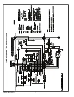
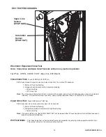
AM7A0C36H31-SF-1A
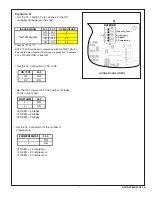
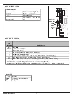
dip Switch S1
Set the S1-1 and S1-2 dip switches for the OD
•
multiplier (tonnage) per the chart.
Set the S1-3 dip switch for AC or HP.
•
OD TYPE
S1‐3
HP
OFF
AC
ON
S1
Airflow Control (AFC)
1
1
1
2
3
4
5
1
2
3
4
5
HP
2 (Compressor)
2 (Stages)
AC (System)
}
OUTDOOR
Capacity (Tons)
OUTDOOR
}
Torque
CFM/Ton
Cool Off Delay
}
INDOOR
CFM
+12V
R13
R14
R1
R4
1
U1
R NET 1
S1
on
on
S2
R NET 2
R
6
C
22
C
19
C
15
C
12
C
18
C
21
C10
D9
L1
R22
Set the S1-4 dip switch for the number of stages
•
on the outdoor unit.
OD STAGES
S1‐4
1
OFF
2
ON
Set the S1-5 dip switch for the number of
•
compressors.
# COMPRESSORS
S1‐5
1
OFF
2
ON
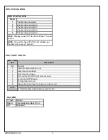
16 SEER = 1 Compressor
19 SEER = 2 Compressors
20 SEER = 2 Compressors
16 SEER = 2 Stages
19 SEER = 2 Stages
20 SEER = 2 Stages
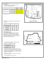
INDOOR MODEL
S1‐1
S1‐2
OD MULTIPLIER
OFF
OFF
3
OFF
ON
2
ON
OFF
2.5
ON
ON
3.5
* May be "A" or "T"
*AM7A0C36H31SA
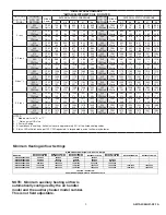
NOTE: The OD multiplier in conjuction with the CFM/TON can
be used to adjust total airflow for your application. Example:
4.5T x 370 CFM/TON = 1665 CFM