TEF 9202 T3/IP66 Ex
ENCLOSURE HEATER USER MANUAL
Electrical connection:
Connect to 220-240V AC 50/60 Hz
Reliability:
Because of the intrinsic self-regulating properties of the
heater, the heater can be used without a thermostat. This
provides, in a single component, a heater that is not vulner-
able to thermostat failure.
Further, the rugged polymer construction of the heater ele-
ment ensures highly reliable performance in harsh and cor-
rosive environments due to the composite housing.
Design flexibility:
Due to the relatively low surface temperature and self-regulat-
ing nature of the heater, components and wires may be lo-
cated close to the heater without fear of damage caused by
overheating. The relatively low profile of the heater makes it
ideal for installation into a range of control and monitoring
panels as well as instrumentation and monitoring cabinets
located on-site.
INSTALLATION INSTRUCTION
Operation:
The Tranberg 9202 Enclosure Heater contains no moving
parts. It may be left without fear of failure through overheat-
ing. The heater may be installed anywhere in the enclosure,
although, for best result, the heater should be mounted to-
wards the base of the enclosure in a horizontal position.
Self-regulating performance:
The enclosure heater contains an element consisting of a
semi-conductive polymer core extruded between two par-
allel copper conductors. This leads to a higher heat-output
at low temperatures, with the power decreasing as the tem-
perature increases. This may help to prevent overheating of
enclosures and components.
Maintenance/Repairs/Modification:
Before disconnecting the heater, make sure that the power
is disconnected. If the enclosure heater failed and is defect,
it should be replaced by a new heater. Modification of the
enclosure heater or change of design is not allowed.
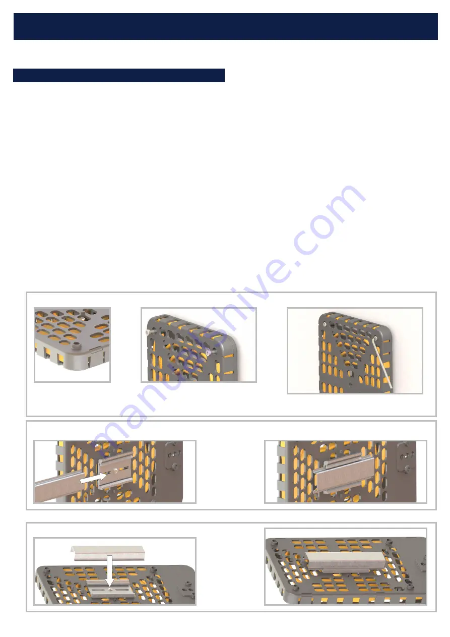
4xM5 mounting holes on the
backside of the heater.
Hold the heater close to the installation
surface, and insert the M5 screws in each
of the 4 mounting holes.
Use a tool to tighten the screws firmly and secur-
ing the heater.
Mounting with screws
After properly fasten-
ing the DIN rail
beneath the heater,
slide the DIN rail onto
the SS35/15 terminal
rail.
Mounting on SS35/7,5 terminal rail
After properly fasten-
ing the DIN rail
beneath the heater,
click the DIN rail onto
the SS35/15 terminal
rail.
Mounting on SS35/15 terminal rail


