background image

Operators manual for the Pentruder 8 – 20HF IQ and Pentpak 427


Page 24 


Tractive Support 


Torque and spindle speed in rpm 

 
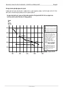
Independent of what size blade is needed, the 4-speed gearbox allows the Pentruder 8-20 HF IQ to 
work with a remarkably high torque at all spindle speeds.  
 

Spindle RPM 

Torque 
Nm  
on the 
spindle 

100 

200 

300 

400 

500 

1200 

400 

800 

600 

1000 

1:st gear 

350 Hz = Potentiometer at 80% 

400 Hz = Potentiometer at 90% 

440 Hz = Potentiometer at 100% 

2:nd gear 

3:rd gear 

4:th gear 

Graph shows torque for a 
fictive, not Tractive, wall saw 
without a multi step 
gearbox. Torque is constant 
up to 950 rpm. Power is 
proportional to rpm. 
Unfortunately, if rpm is 
halved, output in kW is also 
halved.  

kW = Torque in Nm*RPM 
             9550 (constant) 

 
With a gearbox, the motor 
can always work within its 
optimum speed range, and 
power is more or less 
constant. 
 

Torque depending on gear and spindle speed for Pentpak 8-20 HF IQ in comparison 
to fictive wall saw without multi step gearbox 

Содержание Pentpak 427

Страница 1: ...n and mounting of track feet and tracks 13 Mounting the saw head on the track 15 Quick disconnect coupling for HF motor on saw head 16 Quick disconnect coupling for the saw blade 17 Function principle 17 How to fit a blade on a standard blade flange 18 How to fit a blade on a flush cutting flange 18 Peripheral cutting speed and spindle speed 21 Torque and spindle speed in rpm 24 Mounting the blade...

Страница 2: ... 8 20 HF IQ to one of the safest and most efficient machines available on the market today The third section of this manual page 11 32 contains a description how to get started with the machine Please take careful note of the Safety Precautions The fourth section of this manual page 33 40 contains instructions how to maintain the equipment and technical data Important When you read this manual it ...

Страница 3: ... saw head less motor and 15 5 kg 34 lbs for the 27 kW motor The machine is ideal for cutting with blades from Ø 800 32 to 2000 mm 78 diameter Lightweight saw head built from aircraft quality components machined from high tensile strength billet aluminium No castings are used Quick release coupling for the HF motor on the saw head To put the motor on the saw head or to remove it takes just a few se...

Страница 4: ...t for connectors are exposed Travel and feed transmission is by means of planetary gear transmission and a self blocking worm gear transmission No risk for unexpected movements of the saw head as a result of a failed electric motor brake The worm screws are supported by oil lubricated axial needle roller bearings and axial thrust ball bearings The HF motor has a long life multi plate slip clutch f...

Страница 5: ...safety and simplifies awkward set up s considerably especially when flush cutting must be performed The saw blade can always be fitted after the machine is mounted radially and heavy and troublesome set up s can be eliminated to a great extent Mounting a saw blade for flush cutting has always been relatively awkward and often one must mount the saw head and the saw blade together and it can be dif...

Страница 6: ...ed The tracks have stainless steel rails on which the rollers run They offer high wear resistance and precise control of the saw head The grooves into which the guide rails are located have been machined with great precision The tracks are quickly and easily mounted in an easily accessible yoke by means of a T slot piece which in turn is provided with a lubricated and protected screw and case hard...

Страница 7: ...l guide New regulations put new and higher demands on safety and thereby on the blade guards Because of the lightweight design it is more likely that the operator will choose to use the blade guards on all jobs this has not always been so The guards on the Pentruder 8 20 HF IQ are so convenient and lightweight they should always be used It is a basic requirement for safe handling of the machine Sp...

Страница 8: ...rgency Stop buttons are depressed The blade if in rotation and in a cut will continue to rotate because of its inertia but will coast to a stop after a few seconds If the blade is rotating and not in a cut it will take longer before the blade stops No functions remain after the power pack has been shut off At every restart the power pack starts from the same initial mode with all functions reset T...

Страница 9: ... be accepted when the saw head Pentruder 8 20 HF IQ is used together with power packs machines and accessory equipment of Tractive s manufacture and origin Safety precautions It is of paramount importance that the operator has full knowledge and understanding of the instructions below This wall saw may not be used unless the operator is fully familiar with the contents of this manual and has been ...

Страница 10: ...ording to the instructions given in this manual Warning To maintain the level of safety inherent in the design of this machine only Tractive original spare parts may be fitted Tractive AB disclaims all responsibility for damages occurring as a result of use of non original parts Important The power pack should preferably only be operated when it is put on its back with the hour meter pointing upwa...

Страница 11: ... be supplied with clean cold water minimum 4 L minute 1 GPM Water seal on saw head In the saw arm there is a rotating shaft with seals used to feed the water into the centre of the spindle and further to both sides of the blade flange Two seals seal off the water which is fed through the spindle and further on through the blade flange to the blade Just above the coupling clamp screw there is a sma...

Страница 12: ... a 40 Amp fuse if possible Safety precautions on the site Check with the foreman responsible that all necessary precautions have been performed before commencing work Await the approval of the safety precautions and mounting position of the machine from a responsible person before work is commenced Warning If there is a possibility that concrete blocks may fall down causing injury or damage to per...

Страница 13: ...sing a thick washer and anchors of type HKD M12 1 2 or equivalent See picture below Warning Hilti no longer recommends the use of their HKD anchors for fastening wall saw track brackets Use other reliable anchors of the HKD type If the HKD anchors or other high quality expansion anchors can not be fixed securely the track feet must be securely fixed with through bolts and large washers to achieve ...

Страница 14: ...l the way out before the track is mounted Leave at least a turn from the fully out or in position Mounting the track The track is mounted using clamp screws which fit into the yoke of the track foot At least two feet must be used to mount one track The clamp screws are fitted in T slot clamps running in T slots at the rear of the tracks These T slot clamps can be locked in any position by means of...

Страница 15: ...he bottom rollers engaged first Then fold the saw head towards the track to engage the eccentric rollers move head slightly along the track to engage the travel gear with the rack release the locking pins and turn the handles inwards until the locking pins engage again Warning Before the saw is operated always check that the eccentric shafts are locked in position to prevent the saw from falling o...

Страница 16: ... is working To fit the HF motor align the splined drive shaft and clamp studs with the holes in the saw head rotate the saw blade very slowly by hand until the splines fits and motor seats properly Then tighten the clamp screws using the 8 mm Allen T key To remove the HF motor turn the clamp screws three 3 full turns CCW and pull the motor straight out from the saw head Warning To avoid any possib...

Страница 17: ... which then moves inwards The flange and the spindle are provided with drive dogs to transmit the torque to the blade The dogs must always be aligned in mesh for the coupling to work properly At the same time as the pull stud moves inwards a conical centering ring moves outwards to centre the flange on the spindle This ring at the same time interlocks the coupling by blocking the T slot This princ...

Страница 18: ... Slippage will cause irreparable damage to the flanges Clamping The blade is fitted on the inner flange and is clamped by the outer collar with a special centre bolt The centre screw should be tightened to 30 40 Nm Grease the centre bolt and thread regularly The bolt or the female thread in the blade flange may never start to corrode Corrosion of the threads or any part of the bolt may cause failu...

Страница 19: ...likewise Important The blade must have a bolt circle where the holes are spaced on an even and exact pitch to prevent unequal load distribution on the screws blade and flange Look out for cracks around the counter sunk holes in the blade Some blades are prone to crack and if that happens it is potentially a very dangerous situation which can lead to fatal accidents Mounting the blade with flange o...

Страница 20: ...USE A RATCHET TO SHIFT GEARS THE GEAR SELECTION MECHANISM MAY THEN BE DAMAGED Warning The gear selection knob may not be operated before first disconnecting the two power cords from the saw This important rule must always be strictly followed to ensure that the blade motor cannot be inadvertently started Failure to follow this instruction may result in serious personal injury or death The power pa...

Страница 21: ... conditions and size of blade In combination with alteration of the frequency from the HF power pack an infinite speed range from approximately 400 to 1165 RPM is available Spindle speed in rpm and peripheral cutting speed in metres second for different blade diameters with blade speed potentiometer setting at 80 which corresponds to 350Hz Gear Ø 600 Ø 800 Ø 1000 Ø 1200 Ø 1600 Ø 2000 1 405 rpm 12 ...

Страница 22: ...concrete with a high content of steel For 2000 mm blades reduce the HF motor speed to about 80 of max speed this will result in 400 RPM and 43 m s peripheral speed See the first table Full power is available from 80 to 90 of maximum speed At a setting of 100 on the speed potentiometer power is reduced by 0 4 kW Spindle RPM 1200 400 800 600 1000 20 30 40 50 Ø 1200 mm blade Ø 1000 mm blade Ø 800 mm ...

Страница 23: ...w this instruction may result in serious personal injury or death The power pack can be placed out of sight of the operator maybe 30 m s away or on a different level and the only way to protect the operator from accidental starting of the blade motor is for the operator to always disconnect the two power cords With these cords disconnected no power can go to the saw head Spindle RPM 1200 400 800 6...

Страница 24: ...ntiometer at 80 400 Hz Potentiometer at 90 440 Hz Potentiometer at 100 2 nd gear 3 rd gear 4 th gear Graph shows torque for a fictive not Tractive wall saw without a multi step gearbox Torque is constant up to 950 rpm Power is proportional to rpm Unfortunately if rpm is halved output in kW is also halved kW Torque in Nm RPM 9550 constant With a gearbox the motor can always work within its optimum ...

Страница 25: ...nd take off the guard Warning The blade guard has many functions The most important one is to protect the operator and other persons from accidental injury For example in a situation when the operator or someone else accidentally falls against the machine the guard is there to as well as possible protect against contact with the running blade In other potentially dangerous situations for example i...

Страница 26: ...e power pack is water cooled and needs a minimum of 4 litres 1 gallon of cool water per minute at full power output The water pressure should be at least 1 bar 45 PSI and maximum 5 bar 70 PSI The water supply may only be connected to the short hose on the power pack water valve Important In sub zero temperatures the remaining water inside the power pack cooling circuit must be blown out with compr...

Страница 27: ...ected to a 5 pin 380 480 V 3 phase supply with minimum 32 Amp fuses A neutral is NOT needed other than for the 230V single phase supply Connecting to mains The power pack is equipped with a 32 Amp receptacle To use other sizes than 32 Amp plugs an adaptor must be fitted The power pack may be electrically disconnected from the mains when the power cords between the power pack and saw head are conne...

Страница 28: ...feed and travel motors grey remote control cord to the power pack and lastly a 380 480V 3 phase cord to the mains Then press the green push button A green light in the button should then come on Connector for remote control unit Connector for feed and travel motors on saw head Connector for HF motor on saw head Coupling for water from power pack to hose to saw head Coupling for water supply to the...

Страница 29: ...own fuses repair cords repair or replace plugs and receptacles Note To allow capacitors in the inverter to discharge at least one minute must elapse after the emergency stop button is pressed and the green start button is pressed LED indicating status for the power pack One blink Overcurrent alarm May occur if the blade is jammed in the cut Press start blade switch to reset or unplug the unit for ...

Страница 30: ...ure below 110 C LED indicating status for the feed and travel drive system One blink Travel feed not working correctly Two blinks Saw arm feed not working correctly Three blinks Automatic identification of machine type not working correctly Continuously on When this light is on it is an indication that there is a problem with the 24V DC servo that supplies power and control to the feed and travel ...

Страница 31: ...peed is set at 70 of the maximum speed Full power is available when the potentiometer knob is between 85 and 100 on the potentiometer scale At its maximum CW position i e 100 the motor power output is slightly reduced by approximately 0 4 kW Potentiometer for feed and power regulation As long as the blade is spinning in the air the potentiometer is used only to control rapid feed of the machine Fr...

Страница 32: ...or it to reset Certain reset procedures are activated depending on how sudden the stop was If the blade is jammed very very abrupt the reset procedure might not be enough In this case you need to unplug the unit from the power supply wait for 30 seconds and plug it in again NOTE If one of the emergency stop buttons are pressed or the unit has been unplugged from the power supply both the blade spe...

Страница 33: ...high pressure cleaner is used the nozzle may NOT be pointed at rotating parts on the machine Avoid pointing at seals and electrical connectors Cords and connectors Check that all cords and connectors are in faultless condition Track guide rollers Check that the track guide rollers on the saw head can move freely without too much friction A certain amount of friction is always present as the bearin...

Страница 34: ...en necessary Repair kits are NOT available as all wires are crimped to the pins and sockets in the connectors Damaged connectors and cords should be sent to Tractive for repair and or replacement of parts All connectors supplied with the machine when new have crimped pins and sockets and can not be soldered Quick disconnect coup ling for the saw blade The flange and the spindle are provided with d...

Страница 35: ...picture below The seal arrangement is shown in the bottom picture Please note the wear sleeve on the rotating shaft 2 Replace the worn seals with new ones and grease seals with a water resistant grease 3 Use a plastic hammer to lightly tap the seal cartridge in place again 4 If the wear sleeve needs to be replaced the wear sleeve can be pulled off using a special tool Part No 65420100 The new wear...

Страница 36: ...tes The whole assembly must be disassembled cleaned and greased regularly to function well 1 Remove the blade flange from the spindle 2 Remove the 16 M4 countersunk screws and remove the stainless steel ring 3 Remove the 16 M4 Allen Screws and take off the flange 4 Disassemble the various parts and clean in a solvent 5 Grease all parts and replace worn O rings See spare parts manual for part numbe...

Страница 37: ...ear 400 510 rpm 2 nd gear 580 740 rpm 3 rd gear 740 920 rpm 4 th gear 930 1160 rpm 350 440 Hz Travel Motor Max speed 24V DC 1 8 m min Feed Motor Max arm rot Speed 24V DC 0 9 rpm Water feed Central through the blade flanges Blade flange diameter 158 mm 6 22 Bolt circle diameter for flush cutting 130 mm 6x M 8 10 9 countersunk screw 110 mm 6x M 10 10 9 countersunk screw 4 25 6x 3 8 108 mm 6x M 10 10...

Страница 38: ... kW Max continous output power 27 kW 37 HP Minimum fuse 25 Amp The demanded power output must be reduced to about 65 by turning the feed rate knob to 65 Recommended fuse 40 Amp Current draw at max output 56 Amp Recommended diesel generator size 45 kVA Output voltage to feed and travel motors 24V DC Height incl handles connectors etc 28 cm 11 Width incl handles connectors etc 30 cm 11 8 Length 68 c...

Страница 39: ...MC Directive 89 336 EEC amended by 92 31 EEC and 93 68 EEC We also declare that it is compliant with the generic emission standard EN 61000 6 4 2001 and the generic immunity standard EN 61000 6 2 2001 and is CE marked according to the EMC directive 89 336 EEC In accordance with the EC declaration of conformity the product must not be modified without the manufacturer s permission If this occurs th...

Страница 40: ...23 EEC amended by 93 68 EEC EMC Directive 89 336 EEC amended by 92 31 EEC and 93 68 EEC We also declare that it is compliant with the generic emission standard EN 61000 6 4 2001 and the generic immunity standard EN 61000 6 2 2001 and is CE marked according to the EMC directive 89 336 EEC In accordance with the EC declaration of conformity the product must not be modified without the manufacturer s...

Отзывы: