


User's Manual l MBa335x UM 0202 l © 2018, TQ-Systems GmbH
Page 9
4.1.2
I
2
C address mapping
Illustration 3:
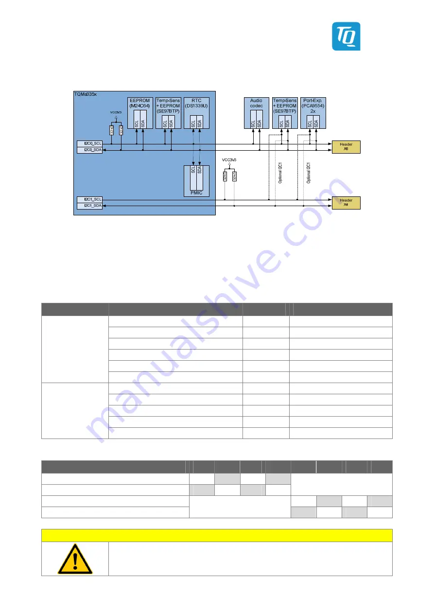
Block diagram I2C bus
Only I2C0 is used on the MBa335x by default. I2C1 is used neither on the MBa335x nor on the TQMa335x by default.
I2C0 and I2C1 are routed to headers on the MBa335x.
Table 7 shows the slave addresses used for this bus as well as the components on the TQMa335x.
The temperature sensor/EEPROM, as well as both port expanders can be controlled with I2C1 by an assembly option on the
MBa335x. See Table 8 for the required assembly option to use the I2C1 bus.
Table 7:
I2C0 slave address mapping (default assembly)
Hardware
Component
Ref.
Address
EEPROM (M24C64)
–
0x50 / 101 0000b
EEPROM (SE97BTP)
–
0x57 / 101 0111b
Temperature sensor (SE97BTP)
–
0x1F / 001 1111b
RTC (DS1339U)
–
0x68 / 110 1000b
PMIC (TPS659)
–
0x2D / 010 1101b
TQMa335x
PMIC (TPS659)
–
0x12 / 001 0010b
Audio codec (TLV320)
N2200
0x18 / 001 1000b
EEPROM (SE97BTP)
D2400
0x51 / 101 0001b
Temperature sensor (SE97BTP)
D2400
0x19 / 001 0001b
Port expander (PCA9554) outputs
D900
0x20 / 010 0000b
MBa335x
Port expander (PCA9554) inputs
D901
0x21 / 010 0001b
Table 8:
Assembly option for port expander and temperature sensor
Option
R900
R901
R902
R903
R2400
R2405
R2406
R2411
Port-Expander at I2C0 (Default assembly)
0 Ω
NP
0 Ω
NP
Port-Expander at I2C1
NP
0 Ω
NP
0 Ω
X
Temperature sensor at I2C0 (Default assembly)
0 Ω
NP
0 Ω
NP
Temperature sensor at I2C1
X
NP
0 Ω
NP
0 Ω
Attention:
Attention when using I2C0. Since the PMIC can be addressed via this interface,
errors on the bus can lead to an instable TQMa335x!


