3
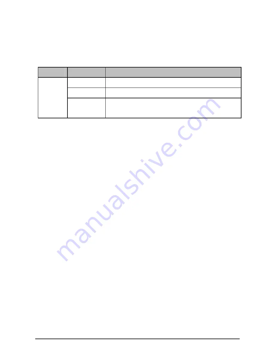
1.3 Description of LEDs
There is an LED for each port, labeled as M1 and M2, on the
panel of TX432. Described below:
LED
Status
Description
Off
The port isn’t connected to any devices.
On
SPF+ port is connected to a device.
M1,M2
Blinking
SPF+ port is connected to a device and
transferring data.
)
Note:
The switch applicable to TX432 will display corresponding LEDs
on its front panel to indicate the port status of the interface card.
For details about the LEDs, please refer to the switch user
guide.
Chapter 2
Installation
2.1 Tools for installation
•
Philips screwdriver
•
ESD-preventive wrist strap
2.2 Installing & Removing the Interface Card
•
Installing the Interface Card to the switch
1.
Wear an ESD-preventive wrist strap, and make sure that it
has good skin contact and is well grounded.
2.
Use a Phillips screwdriver to loosen the mounting screws
of the filler panel on the interface card slot of the switch
(T3700G-28TQ for example) and remove the filler panel,
as shown in Figure 2-1.


