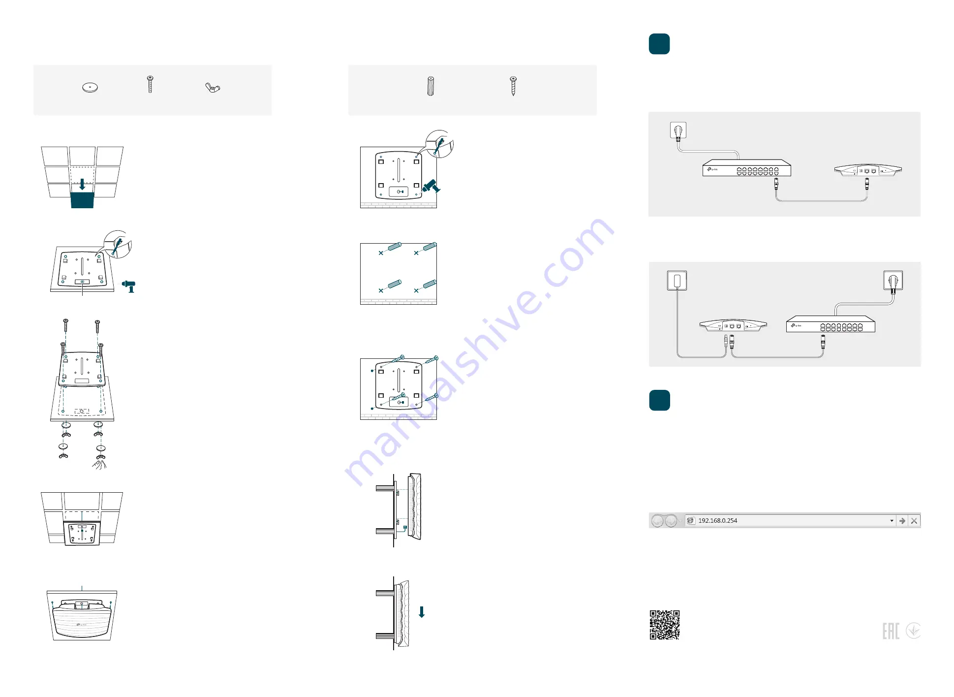
The CAP can be powered via a PSE device (such as a PoE switch) or a power adapter.
Power Supply
Option 3: Wall Mounting
Option 2: Ceiling Mounting
Connect an Ethernet cable from the PoE switch to the PoE port of the CAP.
Via PoE Switch
PoE Switch
3
©2017
TP-Link 7106507575 REV1.0.0
Via Power Adapter
Plug one end of the provided power adapter into the POWER port of the CAP and the other
end to a standard electrical wall outlet.
Switch
M3×20 Self-tapping Screws
(Qty.4)
M3×28 Plastic Wall Anchors
(Qty.4)
5
Push the CAP along the direction of arrows until it
locks into place, and then adjust the cable to make
the exposed part hidden behind the CAP.
4
Feed the Ethernet cable through the hole. Then set
the ceiling tile back into place.
2
Insert the plastic wall anchors into the 6mm holes.
2
Place the mounting bracket in the center of the
ceiling tile. Mark the four positions of the screw
holes and a hole for the Ethernet cable to feed
through.
Drill four 4mm holes for the screws and a 10mm
hole for the Ethernet cable.
1
Remove the ceiling tile.
1
If your Ethernet cable feeds through the wall, you can
position the mounting bracket to make the cable
through the fixing hole. Mark the four positions of the
screw holes and then drill four 6mm holes.
3
Secure the mounting bracket to the wall by driving
the self-tapping screws into the anchors. Make sure
that the shoulders of the mounting bracket are on
the outside.
3
Secure the mounting bracket to the ceiling tile
using four M3x30 pan-head screws, washers and
wing nuts.
4
Connect the Ethernet cable to the Ethernet port on
the CAP and attach the CAP to the mounting
bracket, as shown on the left.
5
Connect the Ethernet cable to the Ethernet port
and push the CAP along the direction of arrows
until it locks into place, as shown on the left. Then
adjust the cable to make the exposed part hidden
behind the CAP.
Hole for Ethernet cable
X4
Wing Nuts
(Qty.4)
Washers
(Qty.4)
M3×30 Pan-head Screws
(Qty.4)
X4
Power Adapter
Note: Install the CAP with the Ethernet port downward.
Software Configuration
Note: The IP address of the wireless controller must be reachable for the CAPs in the network.
In FIT Mode
In FIT mode, the CAP should be managed by the wireless controller. Please refer to the Wireless
Controller User Guide to learn more information about configuring and using the controller.
2
Create a new username and password for login, and then click OK.
4
In FAT Mode
1
Launch a web broswer and enter 192.168.0.254 in the address bar.
3
The configuration page will be shown. For detailed configurations, please visit
http://www.tp-link.com/support to download the User Guide in the download center.
Note: To log in to the device, the IP address of your PC should be set in the same subnet address of the
device. The IP address is 192.168.0.x
(”x” is any number from 1 to 253). Subnet Mask is 255.255.255.0.
RESET
ETH1(PoE)
ETH2
POWER
FIT FAT
RESET
ETH1(PoE)
ETH2
POWER
FIT FAT
The products of TP-Link partly contain software code developed by third parties, including software code subject to
the GNU General Public License (“GPL”). As applicable, the terms of the GPL and any information on obtaining access
to the respective GPL Code used in TP-Link products are available to you in GPL-Code-Centre under
(http://www.tp-link.com/en/support/gpl/).The respective programs are distributed WITHOUT ANY WARRANTY and are
subject to the copyrights of one or more authors. For details, see the GPL Code and other terms of the GPL.
For technical support and other information, please visit
http://www.tp-link.com/support, or simply scan the QR code.


