


Toyota Orderpicker Model
15 Service Manual
Section 7 . Component Procedures
Drive and Brake
Drive Wheel
Drive
Wheel
2.
Install drive wheel mounting bolts. Torque
to 100 ft. lbs. (135.7 Nm).
3. Install bumper plate.
4.
Remove block and lower tractor with jack.
5. Connect power and test operation before
returning truck to service.
Drive Tire Replacement
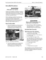
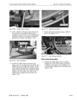
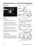
Any misalignment of the tire and hub
while the tire is being pressed onto the
hub can damage the hub. For this
reason, chamfers are provided on the
outside
of the hub and on the end
of the
diameter of the tire's metal
insert. The chamfers help to center the
hub and tire during the pressing
operations and reduce the possibility of
misalignment. To prevent damage, the
hub must be installed on the circular
ram with its chamfered side up.
Outside
of
Hub
Tire
Assembl
y
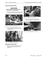
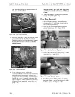
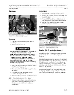
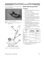
Figure
7-30.
Drive Wheel Mounting Bolts
Removal
1. Turn steering wheel all the way to the right
so you can access drive wheel mounting
bolts. See Figure 7-30.
2.
Turn key switch OFF and disconnect
battery connector.
Use extreme care whenever the truck is
jacked up. Never block the truck
between the mast and the floor. Keep
hands and feet clear from vehicle while
jacking the truck. After the truck is
jacked, place solid blocks beneath it to
support it. DO NOT rely on the jack
alone to support the truck. For details,
see "Jacking Safety" on page
2-1 1.
3. Jack and block truck under tractor frame.
See "Tractor" on page 2- 11.
4.
Remove bumper plate.
5. Remove drive wheel mounting bolts. See
Figure 7-30.
6.
Remove drive wheel.
Installation
1. Install drive wheel on drive wheel shaft.
I I
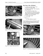
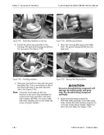
Circular
Ram
Press
Table
Figure
7-3 1 .
Drive Tire
1. Check inside surface of metal insert on
new tire. Use sandpaper to remove any
scaling or rust. Clean inside of metal
insert and lubricate it with a soap
solution.
2.
Place circular ram on the press table. See
Figure 7-3 1. The length of ram must be
00700-CL222-05, 1 5 March 2005
Содержание 7BPUE15
Страница 1: ...Serial Numbers Service Manual 80 001 and up 7BPUE15...
Страница 2: ......
Страница 5: ......
Страница 22: ...Toyota Orderpicker Model 7BPUE15 Service Manual Section 2 Safety Section 2 Safety 00700 CL222 05 15 March 2005...
Страница 58: ......
Страница 128: ...Toyota Orderpicker Model 7BPUE15 Service Manual Section 6 Codes and Tests Code 4 1 00700 CL222 05 15 March 2005...
Страница 144: ......
Страница 168: ...Toyota Orderpicker Model 7BPUE15 Service Manual Section 7 Component Procedures 00700 CL222 05 15 March 2005 7 24a...
Страница 169: ...Section 7 Component Procedures Toyota Orderpicker Model 7BPUE15 Service Manual 7 24b 00700 CL222 05 15 March 2005...
Страница 170: ...Toyota Orderpicker Model 7BPUE15 Service Manual Section 7 Component Procedures 00700 CL222 05 15 March 2005 7 24c...
Страница 171: ...Section 7 Component Procedures Toyota Orderpicker Model 7BPUE15 Service Manual 7 24d 00700 CL222 05 15 March 2005...
Страница 172: ...Toyota Orderpicker Model 7BPUE15 Service Manual Section 7 Component Procedures 00700 CL222 05 15 March 2005 7 24e...
Страница 173: ...Section 7 Component Procedures Toyota Orderpicker Model 7BPUE15 Service Manual 7 24f 00700 CL222 05 15 March 2005...
Страница 174: ...Toyota Orderpicker Model 7BPUE15 Service Manual Section 7 Component Procedures 00700 CL222 05 15 March 2005 7 24g...
Страница 175: ...Section 7 Component Procedures Toyota Orderpicker Model 7BPUE15 Service Manual 7 24h 00700 CL222 05 15 March 2005...
Страница 176: ...Toyota Orderpicker Model 7BPUE15 Service Manual Section 7 Component Procedures 00700 CL222 05 15 March 2005 7 24i...
Страница 177: ...Section 7 Component Procedures Toyota Orderpicker Model 7BPUE15 Service Manual 7 24j 00700 CL222 05 15 March 2005...
Страница 178: ...Toyota Orderpicker Model 7BPUE15 Service Manual Section 7 Component Procedures 00700 CL222 05 15 March 2005 7 24k...
Страница 179: ...Section 7 Component Procedures Toyota Orderpicker Model 7BPUE15 Service Manual 7 24l 00700 CL222 05 15 March 2005...
Страница 180: ...Toyota Orderpicker Model 7BPUE15 Service Manual Section 7 Component Procedures 00700 CL222 05 15 March 2005 7 24m...
Страница 181: ...Section 7 Component Procedures Toyota Orderpicker Model 7BPUE15 Service Manual 7 24n 00700 CL222 05 15 March 2005...
Страница 182: ...Toyota Orderpicker Model 7BPUE15 Service Manual Section 7 Component Procedures 00700 CL222 05 15 March 2005 7 24o...
Страница 183: ...Section 7 Component Procedures Toyota Orderpicker Model 7BPUE15 Service Manual 7 24p 00700 CL222 05 15 March 2005...
Страница 184: ...Toyota Orderpicker Model 7BPUE15 Service Manual Section 7 Component Procedures 00700 CL222 05 15 March 2005 7 24q...
Страница 185: ...Section 7 Component Procedures Toyota Orderpicker Model 7BPUE15 Service Manual 7 24r 00700 CL222 05 15 March 2005...
Страница 186: ...Toyota Orderpicker Model 7BPUE15 Service Manual Section 7 Component Procedures 00700 CL222 05 15 March 2005 7 24s...
Страница 299: ......
Страница 301: ......
Страница 346: ......
Страница 358: ......
Страница 374: ...Toyota Orderpicker Model 7BPUE15 Service Manual Section A Appendix Section A Appendix 00700 CL222 05 15 March 2005...
Страница 386: ...Figure A 6 Cont Elec Schematic Sheet I Part 2 of 2 00700 CL222 05 15 March 2005...
Страница 389: ......
Страница 391: ...Hydraulic Schematic RES Figure A 9 Hydraulic Schematic 00700 CL222 05 15 March 2005...
Страница 399: ...Index Toyota Orderpicker Model 7BPUE15 Service Manual This page intentionallyleft blank 00700 CL222 05 15 March 2005...
Страница 400: ......
Страница 401: ...Printed in the USA...


