IG04B--01
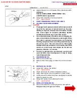
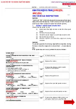
CHECK CONNECTION OF IGNITION COIL AND
IGNITER
SPARK TEST
CHECK RESISTANCE OF HIGH--TENSION
TRY ANOTHER IGNITER
Maximum resistance; 25 k
Ω
per cord
CO RD
CHECK POWER SUPPLY TO IGNITION COIL
AND IGNITER
1. Turn ignition switch to ON.
2. Check that there is battery voltage at
ignition coil positive (+) terminal.
Check wiring between ECM, ignition coil
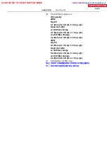
CHECK RESISTANCE OF IGNITION COIL
Cold
Secondary
Hot
9.7 -- 16.7 k
Ω
12.4 -- 19.6 k
Ω
Cold
⊖
Hot
835 -- 1,400 k
Ω
1,060 -- 1,645 k
Ω
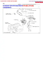
CHECK RESISTANCE OF CAMSHAFT
Cold
NE
and NE
⊖
Hot
1,630 -- 2,740 k
Ω
2,065 -- 3,225 k
Ω
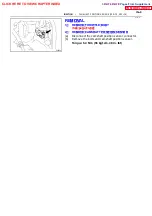
CHECK RESISTANCE OF CRANKSHAFT
CHECK IGT SIGNAL FROM ECM
OK
NO
BAD
OK
OK
OK
OK
OK
Connect securely.
Replace the cord(s).
Check wiring between ignition switch
to ignition coil and igniter.
Replace the ignition coil.
Replace the camshaft position sensor.
Replace the crankshaft position sensor.
with igniter, and then try another ECM.
BAD
BAD
BAD
BAD
BAD
BAD
--
IGNITION
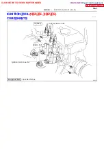
IGNITION SYSTEM (2RZ--FE, 3RZ--FE)
IG--1
IGNITION SYSTEM
(2RZ -- FE,
3RZ -- FE)
ON--VEHICLE INSPECTION
NOTICE:
”Cold” and ”Hot” in the following sentences express the temper-
ature of the coils themselves. ”Cold” is from --10
˚
C (14
˚
F) to 50
˚
C
(122
˚
F) and ”Hot” is from 50
˚
C (122
˚
F) to 100
˚
C (212
˚
F).
1.
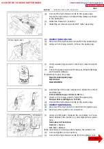
INSPECT IGNITOR AND SPARK TEST
Check that the spark occurs.
(1)
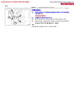
Disconnect the high--tension cords from the spark
plugs.
(2)
Remove the spark plugs.
(3)
Install the spark plugs to each high--tension cord.
(4)
Ground the spark plug.
(5)
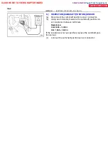
Check if spark occurs while engine is being
cranked.
NOTICE:
To prevent gasoline from being injected from injectors during
this test, crank the engine for no more than 1 -- 2 seconds at a
time.
If the spark does not occur, perform the test as follows:
CLICK HERE TO VIEW CHAPTER INDEX
Pages From Supplement
3RZ-F,3RZ-FE

