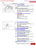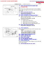
Both intake and exhaust
Bushing bor diameter
Bushing size
mm (in.)
Use STD
Use O/S 0.05
11.000 -- 11.027
(0.4331 -- 0.4341)
11.050 -- 11.077
(0.4350 -- 0.4361)
Z15477
SST
8.2 -- 8.6 mm
Z15478
Sharp 6 mm Reamer
Z00054
44.5
˚
EM0181
Margin Thickness
--
ENGINE MECHANICAL
CYLINDER HEAD (2RZ--FE)
EM--45
(d)
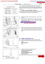
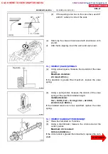
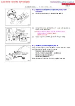
Select a new guide bushing (STD size or O/S 0.05).
If the bushing bore diameter of the cylinder head is greater than
11.027 mm (0.4341 in.), machine the bushing bore to these di-
mension:
11.050 -- 11.077 mm (0.4350 -- 0.4361 in.)
If the bushing bore diameter of the cylinder head is greater than
11.077 mm (0.4361 in.), replace the cylinder head.
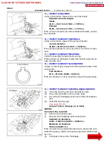
(e)
Gradually heat the cylinder head to 80 -- 100
˚
C (176 --
212
˚
F).
(f)
Using SST and a hammer, tap in a new guide bushing to
where there 8.2 -- 8.6 mm (0.323 -- 0.339 in.) protruding
from the cylinder head.
SST 09201 -- 10000 (09201 -- 01060),
09950 -- 70010 (09951 -- 07150)
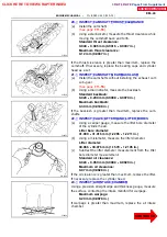
(g)
Using a sharp 6 mm reamer, ream the guide bushing to
obtain the standard specified clearance (See step 9 on
the previous page) between the guide bushing and valve
stem.
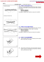
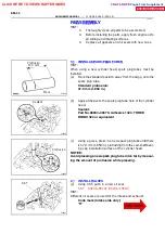
11 . INSPECT AND GRIND VALVES
(a)
Grind the valve enough to remove pits and carbon.
(b)
Check that the valve is ground to the correct valve face
angle.
Valve face angle:
44.5
˚
(c)
Check the valve head margin thickness.
Standard margin thickness:
1.0 mm (0.039 in.)
Minimum margin thickness:
0.5 mm (0.020 in.)
If the margin thickness is less than minimum, replace the valve.
CLICK HERE TO VIEW CHAPTER INDEX
Pages From Supplement
3RZ-F,3RZ-FE

