A02454
START
STA
(--)
(+)
DI--48
--
DIAGNOSTICS
ENGINE (1RZ--E)
S tarter S i gnal Ci rcui t *
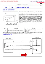
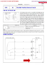
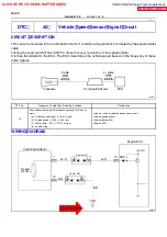
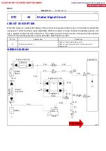
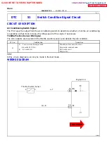
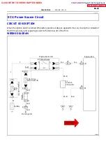
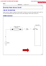
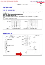
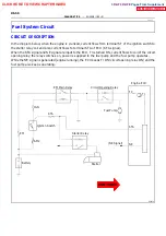
CIRCUIT DESCRIPTION
Refer to DTC43 (Starter Signal Circuit)
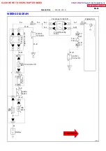
WIRING DIAGRAM
Re fer to page DI -- 42
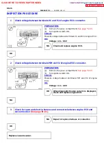
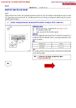
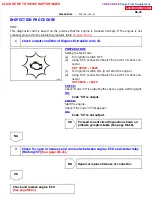
INSPECTION PROCEDURE
HINT:
This diagnostic chart is based on the premise that the engine is being cranked under normal conditions. If
the engine does not crank, proceed to the problem symptoms table on
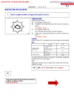
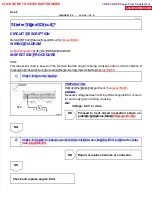
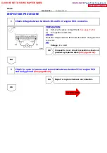
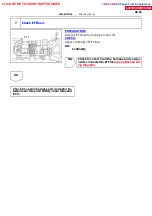
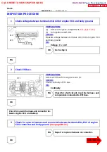
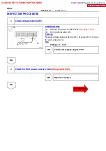
1 Ch eck th e start er sig n al.
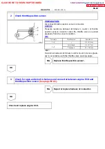
PREPARATION:
Re mo ve the g lo ve co mpartment.
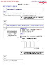
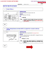
CHE CK:
Measure voltage between terminal STA of engine ECU connec-
tor and body ground during cranking.
OK:
Voltage: 6.0 V or more
OK
Proceed to next circuit inspection shown on
NG
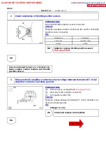
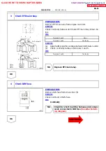
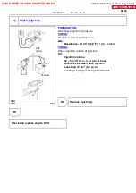
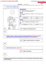
2 Ch eck fo r o p en in h arn ess an d co n n ecto r b etween en g in e ECU an d starter relay
NG
Repair or replace harness or connector.
OK
Check and replace engine ECU.
DI1HX--01
CLICK HERE TO VIEW CHAPTER INDEX
Pages From Supplement
3RZ-F,3RZ-FE


