background image

4

0

10

20

30

40

50

60

70

80

90 100 110 120 130 140 150 160 170 180

1"

2"

3"

4"

5"

6"

7"

0"

TOOLS


Sanding block and paper – GPMR6170


Hobby knife and #11 blades – RMXR6900


Single edge razor blades – HCAR0312


Razor saw (optional)


Razor plane – MASR1510


Electric drill


Small Phillips and flat blade screwdrivers


Pliers with wire cutter


Sealing iron – TOWR3250

 Heat gun – TOWR3200


T-Pins – HCAR5150


Straightedge with scale

Drill bits: 


1/16" 


3/16" 


5/32" 


1/8" 


1/4"

IMPORTANT BUILDING NOTES

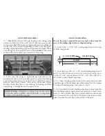
•  Unroll the plan sheets, then reroll the plans inside-out to 

make them lie flat.

•  Using a felt-tip or ballpoint pen, lightly write the part name 

or size on each piece as you remove it from the box. Refer to 
the parts list and plans for sizes and quantities. Use the die-

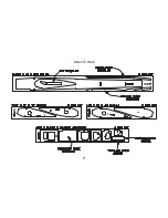
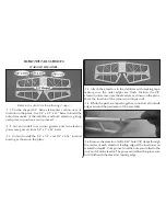
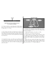
cut patterns shown on page 5 to identify the die-cut parts and 
mark them before removing them from the sheet. Save all 
scraps. If any of the die-cut parts are difficult to remove, 

do 

not force them!

 Instead, cut around the parts with a hobby 

knife or lightly sand the back of the sheet. After removing the 
die-cut parts, use your sanding block to lightly sand the 
edges to remove any die-cutting irregularities.

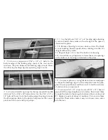
•  Work on a flat surface over the plans. Cover the plans with 

waxed paper. There are notes on the plans that tell you 
what material to use to make each part.

•  When instructed to 

test fit parts

, this means DON’T USE 

GLUE until you are satisfied that everything fits properly – 
THEN glue the parts together if instructed to do so.

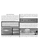
•  The easiest way of cutting balsa sticks is with a razor saw. 

Position the stick over the plan, mark its size, then cut the 
part on a piece of scrap lumber. A modeling miter box works 
well for cutting square corners and 45 degree gussets.

•  A single-edge razor blade also works well for cutting balsa 

sticks. Because the blades are both sharp and thin, they 
don’t crush balsa as easily as #11 hobby blades.

Содержание UPROAR

Страница 1: ...INSTRUCTION MANUAL V 1 4 TUP4P02 Wing Span 48 in Wing Area 573 sq in Weight 3 5 to 4 lb Length 42 in Wing Loading 14 to 16 oz sq ft Engine 32 56 2 stroke 2010 Tower Hobbies ...

Страница 2: ...RUCTION BOOK BEFORE BEGINNING CONSTRUCTION THIS BOOKLET CONTAINS WARNINGS AND PRECAUTIONS REGARDING THE USE OF THIS PRODUCT TABLE OF CONTENTS ITEMS REQUIRED FOR COMPLETION 3 IMPORTANT BUILDING NOTES 4 DIE PATTERNS 5 BUILD THE TAIL SURFACES 6 BUILD THE WING 8 BUILD THE FUSELAGE 12 FINAL ASSEMBLY 15 COVERING AND FINISHING 16 FINAL HOOKUPS AND CHECKS 18 PREFLIGHT 21 FLYING 22 FOLLOW THIS IMPORTANT SA...

Страница 3: ... equipped with an engine like the Tower 40 it s possible to be airborne in a matter of feet zip through three rolls and loop back for a landing before most of your buddies are off the ground What more can we say The Uproar is the most flying fun you can buy regardless of the cost ITEMS REQUIRED FOR COMPLETION HARDWARE We recommend using Great Planes Hobbico and Tower brand accessories for your mod...

Страница 4: ...he sheet Save all scraps If any of the die cut parts are difficult to remove do not force them Instead cut around the parts with a hobby knife or lightly sand the back of the sheet After removing the die cut parts use your sanding block to lightly sand the edges to remove any die cutting irregularities Work on a flat surface over the plans Cover the plans with waxed paper There are notes on the pl...

Страница 5: ...5 DIE CUT PAGE ...

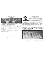
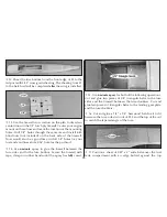
Страница 6: ...rnal bracing as shown on the plans 4 Attach the elevators to the stabilizer with masking tape making sure the outer edges are flush Position the 1 8 elevator joiner wire over the elevators as shown on the plans Mark the location of the joiner wire torque rods 5 While the parts are taped together round off all outside edges around the perimeter of the assembly 6 Remove the elevators Drill a 5 32 ho...

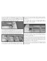
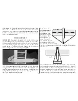
Страница 7: ...e joiner wire Be sure the elevators are flat on the work surface and that the leading edge is perfectly straight FIN AND RUDDER 1 Working over the plans covered with waxed paper assemble the outside framework of the fin and rudder using 1 4 x 1 2 x 30 balsa 2 Add the corner gussets cut from 1 4 x 1 balsa 3 Add the 1 4 x 3 16 balsa internal bracing 4 Using the plans for reference mark and drill a 1...

Страница 8: ... corners WING PANELS 1 Trim the length of the four 1 4 x 1 4 x 30 basswood wing spars to 24 Save the remaining 6 pieces for later use 2 Cover the wing plans with waxed paper Use cross pinning see illustration to hold a wing spar in position where shown on plans The spar should be even with the wing s centerline and tip 3 Cut the four 1 16 x 1 1 8 x 30 balsa trailing edge sheets down to 24 Pin one ...

Страница 9: ... Center the sub leading edge vertically on the front of the ribs and flush with the wing s centerline then glue it in position Sand the top edge flush with the top of the airfoil 7 Cut two 5 16 x 1 3 16 x 30 balsa leading edges to 24 Vertically center then glue a leading edge to the sub leading edge of the wing panel 8 Glue the 1 4 x 1 4 x 24 top basswood spar in position Use a drafting triangle t...

Страница 10: ... clamp the pieces together and phone books or magazines can be used to hold the wing flat ADD WING SHEETING Be sure the wing is pinned flat on your work surface from the spar to the trailing edge before you begin sheeting 1 Glue a 1 16 x 1 1 8 x 24 trailing edge sheet to the top of both wing panels R 1 CAP STRIPS SHEAR WEBS LE SHEET 2 3 8 24 6 2 Trim the four 1 16 x 3 x 30 balsa leading edge sheet...

Страница 11: ... the plans 8 Remove the wing from your work surface Pin it back to your building board upside down making sure that it s straight without any twists 9 Repeat steps 3 8 to sheet the bottom of the wing 10 Use leftover cap strip balsa to frame the servo openings on the bottom of the wing as detailed on the plans 11 Use a razor plane or carving blade and coarse sandpaper to shape the leading edge Cut ...

Страница 12: ...e sure to cut a left and right side Save these pieces for use during final covering 2 Align and glue the top bottom and aft die cut balsa doublers to the die cut balsa right fuse side as shown Be sure the notches on the doublers match the fuse sides perfectly Repeat this operation for the left fuse side but be sure to check your work before using any glue so that you don t make two right sides The...

Страница 13: ... pushrod tube Sand the outside of the tubes to create a better surface for gluing then slide the tubes through the holes in the formers and out through the pushrod exits at the rear of the fuse Glue the tubes to the formers and exit slots with medium CA 9 Cut the rear hatch rail from 1 4 x 1 4 basswood leftover from a main spar Glue it in position into the notches in the fuse doubler at F3 Cut two...

Страница 14: ...and vent lines and a 3 16 hole for the pushrod 14 Use 6 minute epoxy to glue the firewall between the fuse sides and to the fuse bottom Secure the firewall with tape clamps or rubber bands until the epoxy has fully cured 15 Use 6 minute epoxy for both of the following operations Cut and glue two pieces of 3 8 triangular balsa to the fuse sides and the firewall between the fuse doublers Cut and glu...

Страница 15: ...ing from the opposite end Due to the close fit the fuse must be kept perpendicular to the wing or it will bind You will probably need to help each cap strip through the fuse so take your time and work carefully 2 Once the wing is centered in the fuse measure the distance from each wing tip to the tail post Shift the wing until the measurements are equal When wing alignment is correct use medium CA...

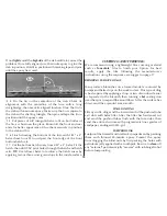
Страница 16: ...two or three cross grain strips to the inside surface COVERING AND FINISHING We recommend using a lightweight film covering material such as TowerKote film to finish your Uproar For best results apply the film following the manufacturer s instructions using the sequence we suggest on page 17 REPAIRING SURFACE DINGS Many surface blemishes on a framed model are caused by bumps and balsa chips on the...

Страница 17: ...ng the sequence that follows Make sure the TowerKote film is thoroughly stuck to the structure and all of the edges are sealed Use a Top Flite Hot Sock on your covering iron to avoid scratching the finish When covering areas that involve sharp junctions like the tail section or around the root end of the wing cut narrow strips 1 4 to 3 8 and apply them in the corners before covering the major surf...

Страница 18: ...om the 6 1 2 piece supplied Cut 8 from the end of both of the 35 wire pushrods with threads on both ends Slide four of the plastic bushings onto each 27 long pushrod wire spaced as shown on the plans If the plastic bushings will not slide on the wire cut them shorter Screw a nylon clevis fourteen revolutions on to each pushrod 5 Remove the backing plate from two nylon control horns then snap a pus...

Страница 19: ...ou are familiar with the flight characteristics of your particular model CONTROL SURFACE THROWS Control throw adjustment By moving the position of the clevis at the control horn toward the outermost hole you will decrease the amount of throw of that control surface Moving it toward the control surface will increase the amount of throw If these adjustments don t accomplish the job you may need to w...

Страница 20: ...use then draw around its perimeter with a felt tip pen Cut away a narrow strip of covering film following the line you just drew Glue the canopy in position with RC 56 canopy glue or thin CA BALANCE YOUR MODEL NOTE This section is VERY important and must NOT be omitted A model that is not properly balanced will be unstable and possibly unflyable 3 1 Accurately mark the balance point on the bottom ...

Страница 21: ...ies the night before you go flying and at other times as recommended by the radio manufacturer GROUND CHECK THE MODEL If you are not thoroughly familiar with the operation of R C models ask an experienced modeler to check if you have installed the radio correctly and that all the control surfaces move in the correct direction The engine operation also must be checked and the engine broken in on th...

Страница 22: ...ane that flies smoothly and predictably yet is highly maneuverable It does not however have the self recovery characteristics of a primary R C trainer therefore you must either have mastered the basics of R C flying or obtained the assistance of a competent R C pilot to help you with your first flights Takeoff If you have dual rates on your transmitter set the switches to high rate for takeoff esp...

Страница 23: ...ilar circumstances unless you can eliminate the slop or flexing in the linkages Here are some things which can result in flutter excessive hinge gap not mounting control horns solidly sloppy fit of clevis pin in horn elasticity present in flexible plastic pushrods side play of pushrod in guide tube caused by tight bends sloppy fit of Z bend in servo arm insufficient glue used when gluing in the el...

Страница 24: ...24 Printed in the USA Two View Drawing You may make copies of this to plan the trim scheme for your Uproar ...

Отзывы: