


User Manual for Machine Vision Cameras
98
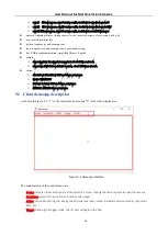
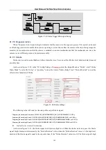
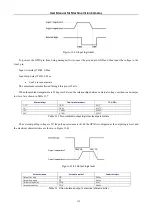
Trigger_in
Trigger
delay
Sensor
exposure1
Sensor
exposure2
Sensor
exposure3
Figure 11
-
10
Frame burst trigger timing
Here is the API code for the setup of the trigger frame value
Toupcam_IoControl(m_hCam, 0, TOUPCAM_IOCONTROLTYPE_SET_BURSTCOUNTER, val, NULL);
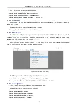
11.4.5
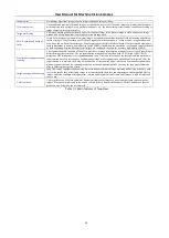
Counter trigger mode
Under this mode, trigger signal number is divided by user
-
defined counter value. For example, when you set the
counter to 3, the camera needs to receive three trigger signals before it can begin exposure, as shown in Figure 11
Trigger
exposure
Sensor
exposure1
Sensor
exposure2
Trigger
delay
Trigger
delay
Figure 11
-
11
Counter trigger mode
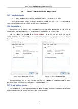
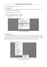
The specific operation in
democpp
are shown in Figure 11
12. First, under "Trigger Source", select the trigger source
as Counter, then click "Counter Source" to select the external trigger source that needs to be divided and configure the
frequency division coefficient in "Counter Value" in the range of 1
-
1023. "Counter Reset" can clear the current frequency
division counter to zero.
Figure 11
-
12
Counter trigger mode setup
The following is the API code for the setup of the counter trigger mode: