


User Manual for Machine Vision Cameras
82
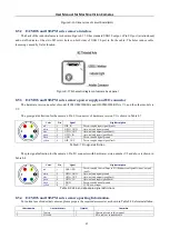
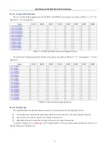
Figure 8
-
16
Dimensions of circuit board(mm)
8.5.2
I3CMOS and I3ISPM series camera interface
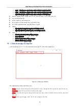
The back of the industrial camera is shown in Figure 8
17. It has standard USB3.0 output, 6 Pin I/O port (aviation head)
and on/off indicator. It has two M2 screw holes on both sides of USB 3.0 port to fix the cable. The holes reduce cable
loosening caused by field vibration.
Figure 8
-
17
Schematic diagram of camera back panel
8.5.3
I3CMOS and I3ISPM series camera power supply and I/O connector
The hardware version number of model I3CMOS00500KMA and I3ISPM00500KPA is V1, and the other models is
V2.
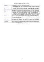
The pin signal definition for the camera 6 Pin I/O connector of hardware version V1 is shown in Table 8
Color
Pin
Signal
Signal description
red
1
DIR_IN
Direct
-
coupled input signal (line2)
white
2
OPTO_GND
Opto
-
isolated signal ground
blue
3
OPTO_OUT
Opto
-
isolated output signal(line1)
green
4
OPTO_IN
Opto
-
isolated input signal(line0)
black
5
GND
Direct
-
coupled signal ground
yellow
6
DIR_OUT
Direct
-
coupled output signal(line3)
Table 8
-
7
Pin signal definition
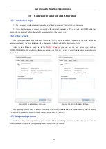
The pin signal definition for the camera 6 Pin I/O connector with hardware version number V2 and above is shown in
Color
Pin
Signal
Signal description
red
1
DIR_GPIO
Direct
-
coupled General Purpose I/O (Software configurable input / output)
(line2)
white
2
OPTO_GND
Opto
-
isolated signal ground
blue
3
OPTO_OUT
Opto
-
isolated output signal(line1)
green
4
OPTO_IN
Opto
-
isolated input signal(line0)
black
5
GND
Direct
-
coupled signal ground
yellow
6
5V
5 VDC power input
Table 8
-
8
V2.0 and above pin signal definitions
8.5.4
I3CMOS and I3ISPM series camera packing Information
For normal use of industrial cameras, please prepare the required accessories as shown in Table 8
9 before installation.
Order number
Accessories name
Quantity
Instruction
1
Camera
1
Camera referred in this manual
2
I/O cable
1
6 Pin cable or extended cable