


User Manual for Machine Vision Cameras
101
Figure 11
-
17
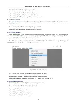
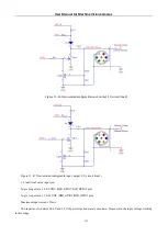
Signal Debounce setup
The following is the API code for the setup of the debouncer time:
Toupcam_IoControl(m_hCam, index, TOUPCAM_IOCONTROLTYPE_SET_DEBOUNCERTIME, val, NULL);
11.7
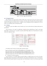
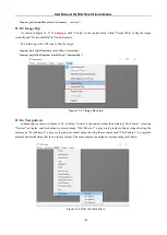
Output signal
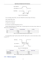
The camera provides 4 output signal modes: Frame Trigger Wait, Exposure Active, Strobe and User Output.
As shown in Figure 11
18, in the "IO Config" dialog, first select the “Isolated output” in the "Line Select" combobox,
then select the output signal mode in the "Output Mode" combobox, click "Output Inverter" to reverse the output signal.
Figure 11
-
18
Output signal mode setup
The following is the API code for the setup of the output signal mode:
Toupcam_IoControl(m_hCam, index, TOUPCAM_IOCONTROLTYPE_SET_OUTPUTMODE, val, NULL);
// Output Mode: 0
-
> Frame Trigger Wait , 1
-
> Exposure Active , 2
-
> Strobe , 3
-
> User output
// index: 0
-
> line0 , 1
-
> line1, 2
-
> line2 , 3
-
> line3
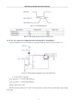
11.7.1
Frame Trigger Wait
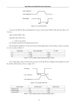
The “Frame Trigger Wait” signal is pulled low at the start of the exposure and is pulled high when the last frame of
data is read out. The trigger signal inputted by the user should be in the valid period of the signal. If the user inputs a trigger
signal when the signal is low, the trigger signal input at this time will be ignored. The following example is the case when
Burst Count = 2, as shown in Figure 11