

Installation Manual
Floorsupport for BalanceBox
®
650
11
1
4
3
2
6
5
10
7
9
8
Contents of the box
Assemble 2x (
5 mm
)
Assemble 6x (
5 mm
)
Assemble 4x (
4 mm
)
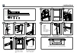
Finish mounting BalanceBox®
650 and application
Insert top and bottom cap
Set height from bottom
(730
–1055 mm / 28.75”-
40,3”) and level; fix (
4
mm
)
Mount all brackets level to
the wall, choose fasteners
suitable for type of wall
Mount BalanceBox® 650
bottom bracket and level
Set height at 925 mm
Mount BalanceBox® 650
At the top
F
I:4x
J:4x
2
0
m
m
B:2x
A:4x
C:3x
D:1x
E:4x
K:4x
G:4x
H:2x
L:4x
2
5
m
m
F:4x
* = not included
Please refer to
BalanceBox® 650
user manual!
Mount cover strips with
double sided tape
G:4x H:4x I:4x J:14x K:4x
E
D
C
J
B
J
D
1
2
S
E
T
H
E
IG
H
T
G
*
*
*
H
I
(
5 mm
)
(* = not included)
9
2
5
(
4 mm
)
I:4x
J:4x
2
0
m
m
B:2x
A:4x
C:3x
D:1x
E:4x
K:4x
G:4x
H:2x
L:4x
2
5
m
m
F:4x
* = not included
I:4x
J:4x
2
0
m
m
B:2x
A:4x
C:3x
D:1x
E:4x
K:4x
G:4x
H:2x
L:4x
2
5
m
m
F:4x
* = not included
A: 4x
B: 2x
C: 3x
D: 4x
E: 2x
F: 1x
A
K
H
I
16"
12"
24"
Additional information when mounting on studded walls
12
I:4x J:4x
2
0
m
m
B:2x
A:4x
C:3x
D:1x
E:4x
K:4x
G:4x H:2x
L:4x
2
5
m
m
F:4x
* = not included
Push cover F on lower
bracket
F


