6
7
Centronics Parallel Interface
PIN
SIGNAL
I/O
DESCRIPTION
1
STROBE-
Input
Synchronize signal Data received
2~9
DATA 0~7
Input/Output
Data bit Transmitted 0~7
10
ACK-
Output
Data receiving completed.
11
BUSY
Output
Impossible to print of data receiving.
12
PE
Output
Paper empty
13
SELECT
Output
Printer status for ON/OFF line
14
AUTO FEED-
Input
Paper auto feed signal
15
GROUND
-
System ground
16
GROUND
-
System ground
17
NC
-
18
LOGIC-H
-
+3.3V
19~30
GROUND
-
System ground
31
INIT-
Input
Initialize
32
ERROR-
Output
Printer error
33
GROUND
-
System ground
34
NC
-
35
NC
-
36
SELLECT IN-
Input
Printer select signal
Ethernet Interface
PIN
SIGNAL
I/O
1
Data Out +
Output Data +
2
Data Out -
Output Data -
3
GND
Ground
4
Data IN +
Input Data +
5
Data IN -
Input Data -
6
N.C
7
N.C
8
N.C
This equipment is indoor use and all the communication wirings are limited to inside of the building.
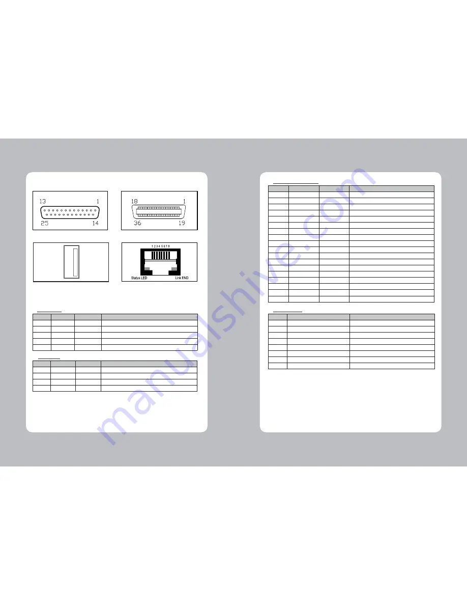
2-2-1. Interface Connector
<D-SUB 25 Female Serial> <Centronics Parallel>
<USB “A” Type>
<Ethernet>
Serial Interface
PIN
SIGNAL
I/O
DESCRIPTION
2
TXD
Output
Printer transmit data line RS-232C level
3
RXD
Input
Printer receive data line RS-232C level
4, 20
DTR
Output
Printer handshake to host line RS-232C level
6
DSR
Input
Data Send Ready
1, 7
GND
-
System Ground
USB Interface
PIN
SIGNAL
I/O
DESCRIPTION
1
+3.3V
-
+3.3V
2
DATA-
-
Printer transmit data line
3
DATA+
-
Printer transmit data line
4
GND
-
System Ground


