1-7. Check and Adjustment
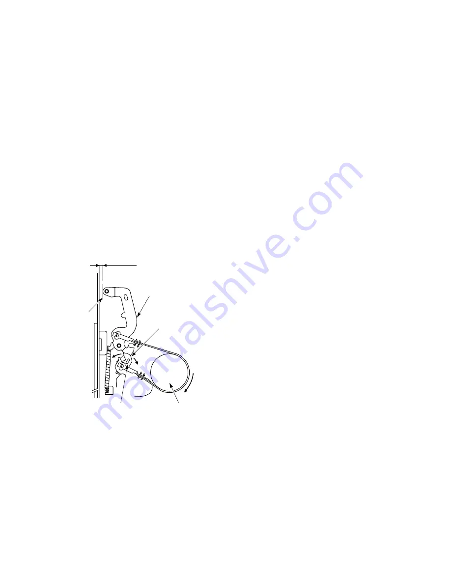
1-7-1. Check of Tension Post Position
1. Turn the worm wheel clockwise after removing the
cassette holder assembly on the front loading
mechanism, and set the cam gear at playback mode.
(Refer to Fig. 1-4-3 Cam Position.)
2. Turn the S reel table (1) clockwise two rounds slowly.
3. While turning the S reel table (1), insert a slot type
screwdriver to the rectangle hole of the adjuster
portion (2) so that the outer periphery of the left end
on the tension lever (3) is put on the marking of the
mechanical deck, and adjust it by turning clockwise
or counterclockwise.
4. After turning the S reel clockwise again, check that
the deviation to the marking is within 1 mm.
Notes:
• There is a long mark at the position of 1.3 mm from
the round surface of the mechanical deck. Make sure
the position of the mark when adjusting.
• When turning the adjuster portion (3), take care
not to apply force in upper and lower directions.
1.3
±
1 mm
Tension lever (3)
Long marking
Adjuster portion (2)
Inserting hole of
slot-type screwdriver
S reel table (1)
Fig. 1-7-1
1-7-2. Reel Torque Check
(1) Reel Torque
1. REV.......................... supply side
Poor torque may not wind the tape. On the other
hand, excessive torque will cause damage to the tape
during REVIEW mode.
2. REC/PLAY .............. take-up side
Poor torque does not rewind the tape to the end. If
excessive torque, the tape may be stretched by
excessive tension.
3. Inspection
Rewind the torque cassette to the end, then check the
torque value shown below:
Review (SP
x
7)
14.2 ± 3.9 mN•m (145 ± 40 g•cm)
REC/PLAY
8.1 ± 2.7 mN•m (82.5 ± 27.5 g•cm)
For the checking method, refer to the following item
(2).
(2) Reel Torque and Back Tension Check
1. Record a signal on the torque cassette tape (KT-
300NR) in the SP mode.
2. Load the torque cassette tape (KT-300NR) in the
VCR and feed it forward until the end of the tape,
before proceeding with measurement.
3. Set the VCR to the REVIEW mode and feed the tape
for about 15s, and then make sure the take-up torque
described above is obtained while observing the left
torque meter.
4. After completion of step “3.”, feed forward to tape
start position and set the VCR to the PLAY mode.
After feeding the tape for about 30s, check the torque
measures 4.4 to 9.8 mN•m (45 to 100 g•cm) reading
the right torque meter. Also, check the back tension
torque measures 4 to 7 mN•m (41 to 71 g•cm) reading
the left torque meter.
5. If the review torque and playback torque are out of
limit specification, replace the clutch assembly.
(Refer to item 1-6-10.)
6. When the clutch gear assembly and the idle lever
assembly, perform the reel torque check.
Содержание W-808
Страница 128: ...9 PC BOARDS 9 1 Main PC Board UZ01 1 A 2 3 4 5 6 7 8 9 10 B C D E F G Fig 9 1 1 ...
Страница 130: ...9 4 KDB PC Board UK04 1 A 2 3 4 5 6 7 8 9 B Fig 9 4 1 10 ...
Страница 134: ...4 3 Chassis Assembly Fig 4 3 1 B001A UZ01 B603B B603C B603 A105 UZ01B UK04 UK01A B601D B601D UK01B HU01 H301 ...
Страница 149: ...438BALEXANDRAROADBLOCKB 06 01ALEXANDRATECHNOPARKSINGAPORE119968 ...


