6
REMOTE CONTROL
(CONTINUED)
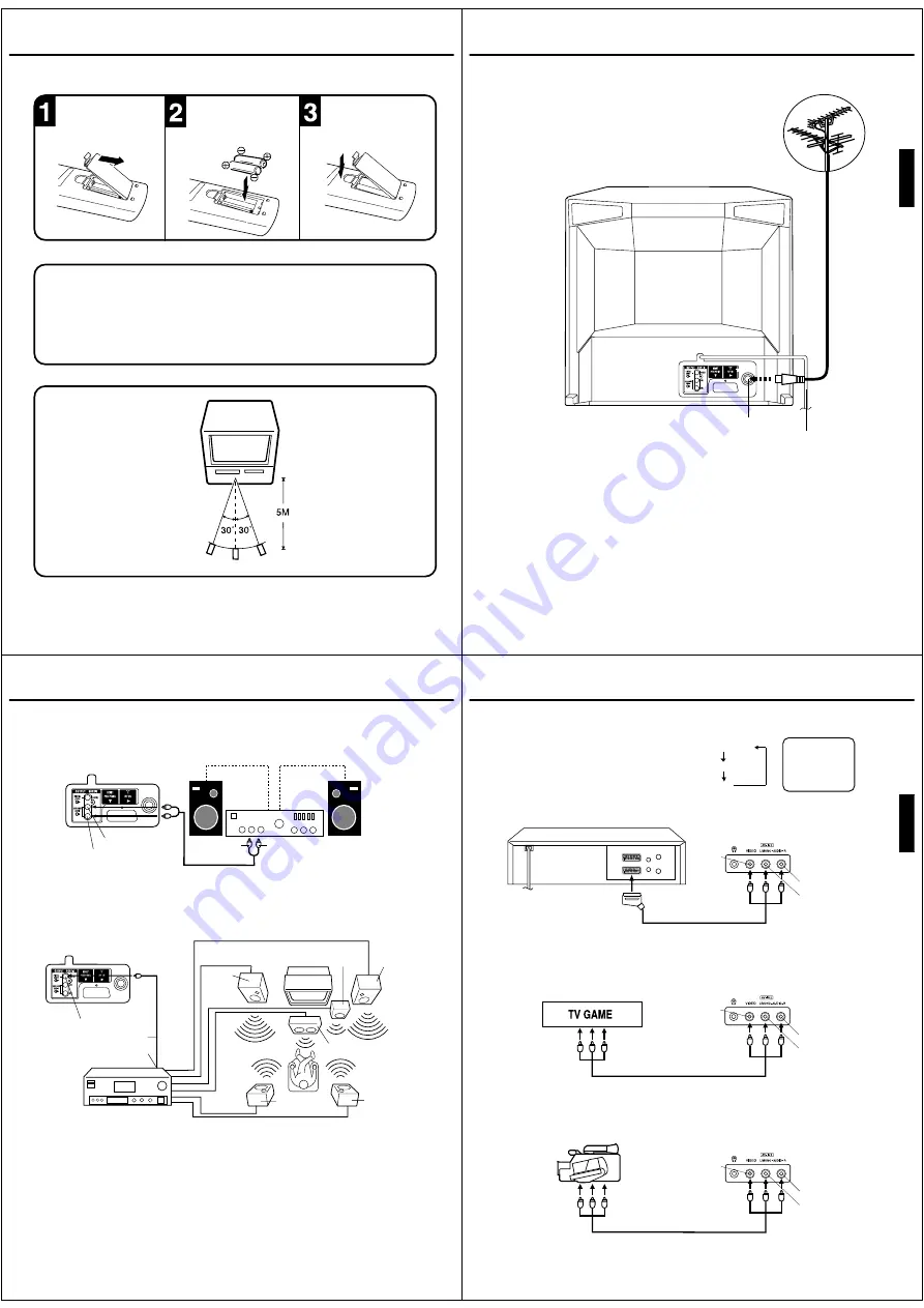
Slide the battery compart-
ment cover in the direction
of the arrow.
Install two “AAA/R03/UM-4”
(penlight size) batteries,
paying attention to the
polarity diagram in the
battery compartment.
Replace the cover.
BATTERY INSTALLATION
•
Use two “AAA/R03/UM-4” size batteries for the remote control transmitter.
•
The batteries may last approximately one year depending on how much the remote control is used. For best
performance it is recommended batteries be replaced on a yearly basis, or when remote operation becomes
erratic.
•
Do not mix old and new batteries.
•
Weak batteries can leak and severely damage the remote control transmitter. Always remove batteries as
soon as they become weak.
•
Dispose of batteries in a designated disposal area.
Never throw batteries into a fire.
BATTERY CAUTIONS
NOTES:
•
When direct sunlight, an incandescent lamp, fluorescent lamp or any other strong light shines on the
remote sensor, the remote operation may be unstable.
•
When there is an obstacle between the unit and the transmitter, the remote control transmitter may
not operate.
EFFECTIVE DISTANCE OF THE REMOTE CONTROL TRANSMITTER
7
ENGLISH
Connect an indoor or outdoor aerial to the aerial socket at the rear panel as shown below.
For all aerial circuit problems, please consult your local dealer.
AERIAL CONNECTIONS
The type of aerial required depends on the position of your home, its distance from the transmitter and local
interference. If you do not have an aerial and you are uncertain of what to buy, you should seek the advice of a local
aerial contractor.
EXTERNAL AERIAL
Aerial socket
Mains lead
8
Using an Audio Amplifier
Using an AV Amplifier with built-in digital surround
If you are using an Amplifier with a built-in digital surround sound decoder (such as Dolby Digital / DTS / MPEG / etc.),
you can connect it as shown below.
Manufactured under license from Dolby Laboratories. “Dolby” and the double-D symbol are trademarks of Dolby
Laboratories.
DTS and DTS Digital Out are trademarks of Digital Theatre Systems, Inc.
*
*
The exact arrangement you use to interconnect various video and audio components to the unit is dependent on the model
and features of each component. Check the Owner's Manual provided with each component for the location of video and
audio inputs and outputs.
To Audio (L) Input
To Audio (R) Input
AUDIO cord (not supplied)
Amplifier
Rear of unit
Coaxial digital cable (not supplied)
AV Amplifier with built-in digital
surround decoder as listed above
Center Speaker
Front
Speaker
(Left)
Front
Speaker
(Right)
Subwoofer
Surround
Speaker (Left)
Surround
Speaker (Right)
Coaxial Digital Audio Output
To Coaxial Digital Audio Input
Rear of unit
This unit
NOTES:
•
•
•
When you make the connections above, make sure that the power of all units is switched off at the mains.
Some DTS decoders which do not support DVD-DTS interface may not work properly with the unit.
When playing DTS encoded material, the sound will only be available through the Digital Audio Output Socket.
Audio (L) Output
Audio (R) Output
CONNECTIONS TO OTHER EQUIPMENT
9
ENGLISH
AV1
Input Selection
If you connect the unit to a VCR, camcorder or games console, you can select this input by pressing the AV button.
3. To connect the TV to a camcorder
To playback from a camcorder, connect the camcorder to the unit as shown.
Press the AV button to select AV2 to use the TV as a monitor.
If you wish to make a recording from the camcorder, follow the same instructions as recording a TV programme (P.24),
but select AV2 for the channel.
Front of unit
2. To connect the TV to a TV Game
The unit can also be used as a display device for many video games. However, due to the wide variety of different types
of signal generated by these devices and subsequent hook-up variations required, they have not all been included in the
suggested connection diagrams. Press the AV button to select AV2 to use the TV as a monitor. You'll need to consult each
component's Owner's Manual for additional information.
1. To connect the unit to a VCR
Press the AV button to select AV2 to use the TV as a monitor.
Camcorder
Front of unit
Front of unit
Audio/Video cord (not supplied)
To Audio/Video OUT
Audio/Video cord (not supplied)
To Audio/Video OUT
VIDEO IN
AUDIO IN (L)
AUDIO IN (R)
Press the TV/VCR button to select the TV mode and
then press the AV button repeatedly to select AV1 or
AV2.
AV1(Scart socket)
AV2(Front-AV-input)
TV-program
To Scart socket
of VCR
Scart cable (supplied)
VIDEO IN
AUDIO IN (L)
AUDIO IN (R)
VIDEO IN
AUDIO IN (L)
AUDIO IN (R)
4. To connect the unit to another TV set (ie. a widescreen set)
Connect this unit to the other TV set using the SCART connection.
You should select the external input setting on the other TV, eg. AV/EXT/etc.
CONNECTIONS TO OTHER EQUIPMENT


