background image

Содержание Tosvert VF-A5

Страница 1: ...Inverter Corporation NOTICE 1 Make sure that this Instruction Manual is delivered to the end user of the inverter unit 2 Read this manual before installing or operating the inverter unit and store it in a safe place for reference TOSHIBA Corporation 1994 All Rights Reserved E6580516 Toshiba Tosvert VF A5 user manual ...

Страница 2: ...n When cover is removed 1 This inverter has a retry function that automatically resets the unit when a fault trip occurs Observe the following points when this function is selected Even if the inverter has fault tripped take care to not get caught in the motor or equipment When the retry function is selected the inverter will automatically start after the designated time Refer to page 83 Take spec...

Страница 3: ...ntrol current limit retry and stall prevention functions are built in so that the inverter will not trip easily and will provide unparalleled reliabilty Please read this manual thoroughly before use to properly understand the correct use of the outstanding functions of the VF AS This manual should be stored by the user of the VF AS for reference during maintenance and inspection Symbols used in th...

Страница 4: ...7 3 4 JOG Run Mode 44 7 4 Operation Mode Selection 45 7 4 1 Operation Mode Changeover 45 7 4 2 Run Stop Command nOd in Lf1 45 7 4 3 Frequency Command Source Setting Function F noc1 in Lf1 J 45 7 4 4 Parameter Setting Function F nOd in Uc 46 7 4 5 Standard Parameter Value Reset Function 1 IF in U 47 7 4 6 Selection of Stopping Method from the Panel 48 7 4 7 Fault Reset 49 8 Parameter Explanations 5...

Страница 5: ...n selection 67 4 S Run frequency control 68 Start up frequency End frequency 69 Jump frequencies 70 PWM carrier frequency 71 5 SF Preset speed operation CD 72 Preset speed operation 73 Frequency priority selections 74 Jogging operation 75 Frequency setting input signal characteristics 76 6 P Electronic thermal protection CD 77 Electronic thermal protection 78 DC injection braking settings CD 79 DC...

Страница 6: ...ting 105 11 1 Inverter Trip Causes and Remedies 105 11 2 Other Fault Troubleshooting 109 12 Maintenance and Inspection 11o 12 1 Preventive Maintenance and Periodic Inspection 110 12 2 Component Replacement 111 13 Storage 112 14 Warranty 112 Appendix Appendix Table 1 Parameter list 113 Appendix Table 2 List of trips 129 Appendix Figure 1 Input terminal information 130 Appendix Figure 2 Output termi...

Страница 7: ...8 DC power source input 200V class output 9 DC power source input 400V class output Model No Type II Model I Option PCB and special specification d s lvlFIAlsl l21ol3l7IPIYl IAl2l2l T I I T Standard Additional motor functions Option PCB and special specification codes capacity E Fully enclosed 0 4kW 004 F External 0 75kW 007 heatsink 1 5kW 015 N GTR7 2 2kW 022 modification 3 7kW 037 Y Other 5 5kW ...

Страница 8: ...xciting coil Resistors Keep away from the inverter Ground the G E terminal to prevent electrical shock and malfunction due to noise Attach the unit to a non combustible material such as a metal panel To ensure adequate ventilation maintain the following installation spaces and always install the unit vertically in the longitudinal direction When installing multiple inverters in a row leave a clear...

Страница 9: ...lly sealed applications 3 2 Removal of Cover CZ ROM interface window removable Refer to section 3 3 Removal of ROM inetrface window Cover Always read the cautions on the front of the cover and remove the cover when wiring Refer to section 3 2 Removal of cover If the ambient temperature of the inverter unit exceeds 40 C when mounted in a panel remove the cover The unit can then be used up to a temp...

Страница 10: ...Option ROM socket ROM cover Option connector 20 pin 8 4 L E6580516 Ill The operation panel attachment screw can now be seen Turn it in the direction of the arrow Ill unit it completely loosens V When the screw has completely loosened pull the operation panal out in the direction of the arrow V Operation panel connector Operation panel attachment stud Changeover switch for frequency setting signal ...

Страница 11: ...f the VF A5 is performed by use of an overload detection circuit electronic thermal relay that meets a general purpose motor s reduced load characteristics The reference current value for this electronic thermal relay is set to the inverter s rated current value therefore this may need adjustment depending on the motor When operating at a frequency that exceeds 60Hz motor vibration and noise will ...

Страница 12: ...tops if the inverter s ST to CC control terminal connection is released so use of the circuit configuration in Fig 4 1 is recommended In Fig a the brake power is turned ON and OFF via MC2 and MC3 If a circuit configuration as shown in the drawing is not used a bound current may flow during braking and may cause an overcurrent trip The brake power can also be turned ON and OFF using the low speed s...

Страница 13: ...or with power factor improvement capacitors installed remove the capacitors or the inverter may fault trip or the capacitors may be damaged u Power factor improvement capacitors or surge absorbers Use with voltage sources other than the rated voltage is not possible If necessary use a transformer etc to increase or decrease the source voltage to the rated voltage A DSA lightning surge absorber is ...

Страница 14: ...2 so that a selective shutdown can be executed and only MCCB2 trips If the optimum characteristics cannot be selected install a high speed shut off fuse after MCCB2 Refer to page 14 for MCCB selection 4 3 Inverter Disposal Precautions Observe the following points when disposing of the inverter Explosions from incineration Gasses from plastics Disposal method Placing the inverter in an incinerator ...

Страница 15: ...fore turning the power on To prevent problems due to radio frequency noise etc do not bundle the wiring to the input power terminals R L1 S L2 T L3 and the motor terminals UfT1 V T2 WfT3 together In order to maintain the control power supply to display faults or to operate the communication options while the main circuit power is shut down remove the two shorting bars between R L1 RO S L2 SO on th...

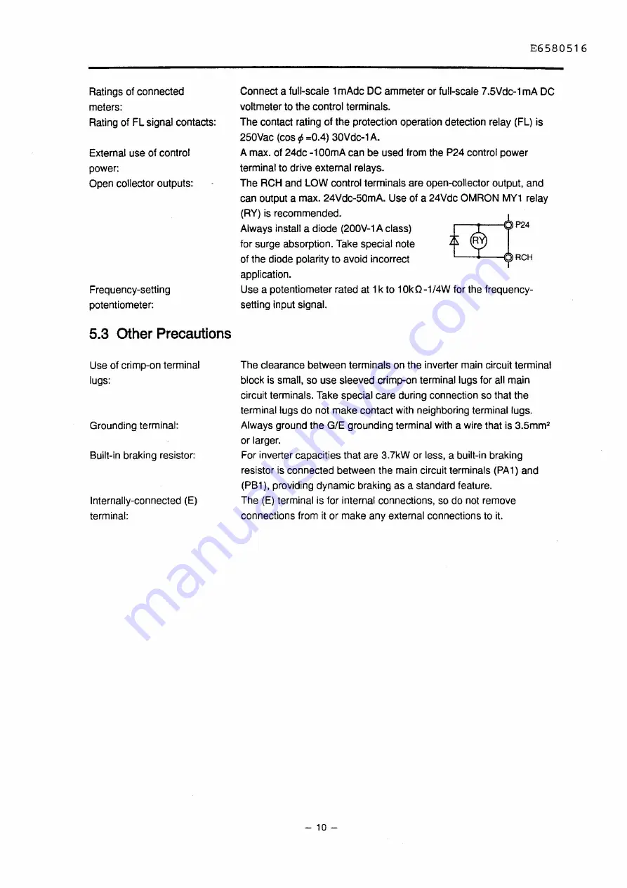
Страница 16: ...y RY is recommended Always install a diode 200V 1 A class for surge absorption Take special note of the diode polarity to avoid incorrect application P24 RCH Use a potentiometer rated at 1k to 1Ok Q 1 4W for the frequency setting input signal The clearance between terminals on the inverter main circuit terminal block is small so use sleeved crimp on terminal lugs for all main circuit terminals Tak...

Страница 17: ...1 When using an external braking resistor install a magnetic contactor MC or non fuse breaker with trip coil MCCB on the inverter s power supply input side for protection Make sure that the power circuit can be opened with the built in fault detection relay FL 2 The VF AS has a built in fault detection relay FL Connect the contacts of this relay to the primary side magnetic contactor MC operation ...

Страница 18: ... Installation of overload relay thermal relay Refer to page 14 Examples of selecting equipment for wiring 1 The VF AS has a built in overload protection function that uses an electronic thermal relay However in the following cases the thermal relay operation level must be adjusted or an overload relay matching the motor s characteristics must be installed between the inverter and motor CD When usi...

Страница 19: ...ay cause radio wave interference to audio equipment etc used near the inverter In this case install a radio noise reduction filter optional on the inverter s power source side or shield the cables to the motor with a conduit to reduce the interference Contact your dealer for further details Cautions concerning ground faults Verify that there are no incorrect connections between the motor and inver...

Страница 20: ...T13J 2 0 3 7 4037P 15 SS30 9 C13J 6 8 T13J 2 0 5 5 4055P 30 SS30 17 C20J 11 T13J 3 5 2 0 7 5 4075P 30 SS30 17 C20J 15 T20J 5 5 3 5 2 0 11 4110P 50 ES50 33 C35J 22 T35J Marcon 8 5 5 15 4150P 60 EH1008 48 C50J 28 T35J Electronics 8 8 0 3 5 18 5 4185P 75 EH100B 48 C50J 35 T65J RFM2H104KD 14 14 400V 22 4220P 100 EH100B 48 C50J 44 T65J 400V system 22 8 0 class 30 4300P 125 EH225 80 C80A 57 T65J Note6 3...

Страница 21: ...tion Note 1 I i Od I set to 2 Press BQ to start running I n0 d I set to I Press IPANEUREMOTE I then IRUN Ito start running Refer to page 33 7 2 Basic Operation for the operation methods Note 2 IF nOd I set to 2 The reference frequency can be set only from the operation panel IF nOd I set to I Press IPANEUREMOTE I and the reference frequency can be entered from the operation panel Example 2 To set ...

Страница 22: ... Note 5 Refer to page 74 Example 4 To set operating frequency forward reverse run decelerated stop and coast stop via external signals 3 phase main circuit MCCB power source 0 0 0 D Potentio meter C2 0 10Vdc _ 3 4 20mAdc t_ __ or 0 10Vdc Setting Parameter group Uo Motor V IM Wo Parameter c ut n Id Command mode selection c ut F n Id Frequency setting mode selection External operating SF FC Setting ...

Страница 23: ...braking resistor with 3 7kW and smaller units avoid the use of an external braking resistor However parallel connection is possible in the following combinations For max braking rate applications Built in braking Minimum external resistor Min total braking value that can be used with the resistor built in braking resistor resistance value 200V systems 2 2kW and smaller 700 700 350 3 7kW 400 400 20...

Страница 24: ... to the built in braking resistor E This is for internal connections so do not remove or connect external A wires This is wired to the inverter chassis Table 6 2 2 Main circuit terminal functions for 5 SkW and larger units Main circuit terminal functions for 5 5kW and larger units are as shown below The internal circuit diagrams for each terminal are shown on page 21 Internal Terminal symbol Termi...

Страница 25: ...tput frequency FM This is a multifunction programmable analog output refer to page 94 I The standard setting is the pre compensation reference frequency When connecting a meter use a 1mAdc full scale ammeter or 7 5Vdc 1mA full scale voltmeter AM This is a multifunction programmable analog output refer to page 94 I The standard setting is the output current When connecting a meter use a 1mAdc full ...

Страница 26: ...C in ON condition The motor will reverse run when both F CC and R CC are short c 0 circuited S1 The standard setting is preset speed run with a short circuit 0 c ctl between S1 CC E S2 E The standard setting is preset speed run with a short circuit 0 Ol between S2 CC a S3 0 The standard setting is preset speed run with a short circuit 0 c between S3 CC a S4 The standard setting is preset speed run...

Страница 27: ... 5 5 7 5kW PB a PA 0 0 l J r i f PO e PC 0 U T1 V T2 W T3 Z z Sym bol 21 E6580516 Internal circuit diagram 11 18 5kW PB PA PO PC 0 a 0 f a 22kW and larger l J irz _J e t 1 i e PC cm l 11 r RlOO f lectrolyttecapacrtor RO 011 r __ l SQ g ICOl l Mu PMkiMllll enl 1 _iercapodty amint durtng aipaclty mu Input R100 c 200V 7 51 W and smaller SOVA 20A 3mS 160 100 F system 30kW and smaller SOVA 20A 7mS 160 ...

Страница 28: ... 0 1 OVdc 0 20mAdc 18k IV o T r O r AID converter SWI 5Vmax Note 1 V 15 k 0 1µT sooo cc Q 1 0 1 OVdc switch at V side 4 20mAdc switch at I side I Analog input 5V 0 10Vdc 0 5Vdc Voltage converter circuit 1k 13k 33k 0 1 µ Note 1 cc 0 0 5Vdc switch at 5 side 0 1 OVdc switch at 10 side cc I i G E Grounding capacitor 22µF Contact inputs 24V 4 7k ST s1 s l o 1 i 2c 7k f RES 10k 0 1 µ 10k AID converter 2...

Страница 29: ...E6580516 Terminal block PCB ST CC shorting bar Fig 6 2 2 Control terminal block 23 23 M3X6L screws Recommended tightening torque 0 5N m 4 41bs in ...

Страница 30: ...shown on the right and remove the shorting bar e m n MOTOR E6580516 With terminal cover Recommended tightening torque 1 2N m 11lbs in Connected to inverter chassis Wired to bulit in braking resistor When using the built in braking resistor change the wiring from PR1 to PB1 Shorting bar When connecting a separate power supply to the RO and SO terminals always remove the shorting bars or the inverte...

Страница 31: ...ock cover lcAUTIONI 4 M4X8L screws E6580516 Connected to the main circuit terminals Do not connect external wiring to the lower terminals With terminal cover When connecting a separate power supply to the RO and SO terminals always remove the shorting bars or the inverter may be damaged Recommended RO SO tightening torque 1 2N m 11 lbs in CONTROL POWER SUPPLY 200V CLASS Note 400V systems are indic...

Страница 32: ...ective covers e 0 1 e QPTL u 1 v iT2 lyt I3 l J CJ L __MOTOR J f RO and SO terminal When connecting a separate power supply to the RO and SO terminals always remove the shorting bars Terminal block Connected to the main circuit terminals Do not connect external wiring to the lower terminals Terminal cover lcAUTIONI RO SO 4 M4XBL screws With terminal cover Recommended tightening torque 1 2N m 11 lb...

Страница 33: ...cting a separate power supply to the RO and SO terminals always remove the shorting bars or the inverter may be damaged earth Terminal block cover lcAUTIONI Terminal block Connected to the main circuit terminals Do not connect external wiring to the lower terminals 4 M4X8L screws With terminal cover Recommended RO so tightening torque 1 2N m 11 lbs in CONTROL POWER SUPPLY 200V CLASS Note 400V syst...

Страница 34: ...istor PA PC DC bus P N connections R M8X20L screw slotted hex bolt s T Main circuit power supply inputs M8X14L screw slotted hex bolt M4X8L screw u v w v Motor outputs ROSO R20S20 GIE Control Operation power power supply supply outputs inputs Fig 6 2 7 Main circuit terminal block 37kW to 75kW units 28 E6580516 ...

Страница 35: ...r Motor outputs DCL unit supply inputs M5 screw Note Shipped with a shorting bar installed Control circuit terminal M4screw RO SO R20S20 v v Control Operation power power supply supply inputs outputs Fig 6 2 8 Main circuit terminal block 11 O t N and 132kW units 29 E6580516 ...

Страница 36: ...uit power suply inputs u v w y Motor outputs PO PA E v v DCL unit Earth Note Shipped with a shorting bar installed Control circuit terminal RO SO R20S20 y 1 y 1 Control Operation power power supply supply inputs outputs Fig 6 2 9 Main circuit terminal block 160kW units 30 E6580516 ...

Страница 37: ...it Earth Note Shipped with a shorting bar installed Control circuit terminal RO SO R20S20 Control Operation power power supply supply inputs outputs 400V 220kW RO SO R20 S20 FU1FU2 Control Operation FUR FUT power power supply supply inputs outputs 400V 2BOkW Fig 6 2 1 OMain circuit terminal block 220kW and 280kW units 31 E6580516 ...

Страница 38: ...page 131 Lights during option priority operation Refer to the Instruction Manual for the oprion for details Units LEDs l l When a numerical value is displayed it can be incremented decremented _ _ _ _ _ with these keys When a When a numerical value is displayed on the LED display the LED corresponding to the numerical value s units will light No LEDs will be lit when A or V units are selected I sy...

Страница 39: ...will light and operation from the panel will be possible If this key is pressed again the panel control LED will go out and remote operation mode from the control terminal block will once again be entered 3 Set the operating frequency The frequency command value can be incremented decremented with the UP key 6 or DOWN key V When one of these keys is pressed the 8 LED display will blink indicating ...

Страница 40: ...ng value has been changed by the user and the changed setting value differs from the standard default setting Auto edit function The parameter settings can also be changed in this group However if a parameter setting value that is the same as the default setting is once again input that parameter will no longer be displayed in this group U sequentially compares the settings of all parameters to th...

Страница 41: ...rs Pl Pattern run parameters uI Utility parameters Cb Feedback parameters c n1 Motor parameters The following parameters cannot be changed while running so stop first and then set them F Fl I ul SL Pl Lfl RF L Max frequency Maximum voltage frequency voltage selection V f pattern Industrial application parameters selection Standard setting mode selection F b c n1 PC Pl I nt P n1 1 PG input No of ph...

Страница 42: ...is displayed press I I IENTER Ito display the current parameter value 8 Ut I l 5nn W t f 5 er n Change the parameter value with the L V keys t l U I When the desired parameter value is displayed press t lt I c I ENTER Ito save it After the parameter name and data 8 t t I I are alternately displayed the parameter name will once Wt I again be displayed 6 1 ENTER I or IPRGI or IMONI or l l l l Return...

Страница 43: ...e can be entered by pressing IMON Iand settings monitor mode by pressing IPRG I Standard monitor mode will once again be entered if the same key is pressed again If the frequency command value is changed while running the operating frequency will change according to the new value If the command value is ahead of the operating frequency the motor will accelerate or decelerate according to the accel...

Страница 44: ...rent during constant speed run I Load end short circuit output terminal check trip during start up _ _ _ oc c I U phase short circuit I OCA2 V phase short circuit oc c 3 W phase short circuit OP I Overvoltage during acceleration I 0F 2 Overvoltage during deceleration OP3 Overvoltage during constant speed run I Inverter overload trip _ _ _ wr_ Motor overload trip oc Dynamic braking resistor overcur...

Страница 45: ...f there are past trips the trip status information for a max of four trips can be displayed in the same manner If IMON Iis pressed the initial display will be returned to If the key is held down during the above steps the display will change to the next item every 0 5 sec The trip title display state can be changed to if the IMON Ikey is pressed at any time The trip status monitor function will re...

Страница 46: ...operating frequency is displayed 8 F F Run direction Forward run F reverse run Note 1 21 so a Operating frequency command value Note 2 1TIQ J r 11 11Uo1 I Jn Ur UI 21 inn Load current A monitor Note 2 lno 21 c we 21 1 1200 Input voltage V monitor Notes 2 and 3 lno 31 21 P200 Output voltage V monitor Notes 2 and 4 lno iii 21 R Input terminal status monitor 21 o Input terminal status monitor 21 I II...

Страница 47: ...point in the process The _ _symbol in the example indicates that the left and right symbols are alternately displayed every 0 5 sec 7 3 3 Setting Monitor Mode This mode is entered by pressing the I PRGI key in standard monitor mode To exit this mode press the IPRG Ikey to move to standard monitor mode or the IMON Ikey to move to status monitor mode As described below this mode both displays parame...

Страница 48: ...oup The first parameter name will be displayed FnSL J FnSL Select the parameter name The parameter name will change when A V are pressed F n 5 L F n FIn 5 L Rn 8 FnSL Set the parameter The parameter setting will be displayed Select the FM terminal function with the 6 V keys to output 1 1 J FnSL the pre compensation reference frequency a Set the data 8 J Fn Display the next parameter name 8 so a Se...

Страница 49: ...I such as the preset speed frequency parameters cannot exceed the values of IL L Iand IO When the IF1 11 IUL Ior IL L Iparameter values are changed the setting values of some parameter may exceed their limits as a result In this case an alarm will be displayed when a parameter with a setting exceeding its adjustment range is selected and adjustent is attempted To change a parameter with this type ...

Страница 50: ...ce is pressed PRG FJOG The JOG mode will be entered when the IPRG Ikey is pressed the second time only if panel control mode is selected and the JOG run frequency setting value is not OHz Forward JOG If panel control mode is not selected or the JOG run frequency is not set operation will return to standard monitor mode frequency display when the IPRG Ikey is pressed the second time 2 Execute rever...

Страница 51: ...e input mode is preset as explained below The panel control LED will be lit when panel operation is selected 7 4 2 Run stop Command i ilOdl in G LJ1 The following sources can be selected for run stop commands command mode n0 cl setting r1 _ I I c 3 _ I Function Only RS232C input valid Terminal block input valid Note Panel input valid Communication option board input valid Panel terminal changeover...

Страница 52: ...ws p n0 d setting Function n Prohibit all key operations w Can perform reset f 2 Can perform monitor operations I Can perform emergency stop B Can perform run stop operations 16 Can perform parameter read operations 32 Can perform parameter change operations 53 Standard mode all operations valid If IF n d Iis set to 3 I reset operations and 2 monitor operations will be valid 46 ...

Страница 53: ...ys 4 1 I Standard setting for 50Hz applications See Fig 7 5 2 Standard setting for 60Hz applications See Fig 7 5 3 Return to factory settings Fig 7 5 Note 2 _I Trip clear S Save user set parameters 6 TYP 5 reset 8 f 11 1 Initialize inverter typeform Note 3 When the desired data is displayed press the IENTERIkey 11 will be displayed and operation will return to standard monitor mode Notice 1 When I...

Страница 54: ... Operation Method and setting Coast stop The power output to This is possible only when operation from the panel is the motor from the valid inverter is shut off 1 Press IPANEUREMOTE Iduring panel run so the motor will 2 Standard monitor mode will be entered and the LED coast and then will display Cc L stop 3 Coast stop will be activated by pressing I STOP RESETI If another key is pressed the Cl L...

Страница 55: ...f the cause is not removed Reset the tripped state with one of the following methods Reset 1 Turn off the power until the LED display goes out Note 1 2 External signal short circuit between control terminals RES CC 3 Panel operation Resetting with the panel is performed by the following process 1 Press ISTOP RESETIand confirm that L is displayed Note 1 Refer to P It CL I page 85 2 Press ISTOP RESE...

Страница 56: ... set to Output voltage M Vo 0 ___Input voltage High Low lwLSLsetto 1 2 Output voltage M Input voltage High 1Low ulu 1 lul I IF 1 Output frequency Hz Set to O Vo fluctuates according to the input voltage Set to Output frequency Hz Vo is automatically set between the following values according to the input voltage when the power is turned on 200V class 200 to 230Vac 400V class 380 to 460Vac Set to c...

Страница 57: ...ter capacity If a standard motor matching the inverter capacity is used the value does not necessarily need to be adjusted Even when readjusting setting to within 2 of the initial setting value is recommended I Pc set to I Automatic torque boost Output voltage 100 Iwl output frequency Hz I Pc set to l I Automatic torque boost with automatic energy saving c _c_s_e_t to S I Vector control Motor spee...

Страница 58: ...uto tuning but the torque will drop slightly near 60Hz The vector control function will operate properly with adequate torque and little speed fluctuation when used below the maximum voltage frequency setting value However in situations where the maximum voltage frequency is exceeded field weakening area the same type of characteristics may not be achieved The maximum voltage frequency setting ran...

Страница 59: ...time IdE I is the time to reach OHz from the max frequency IF1 11 E6580516 The setting adjustment range and resolution can be set by the Ace Dec time units selection IdSt l I Output frequency Hz RCC I lc EC I Time S I E E IRcc I C EC2 The default acceleration deceleration time settings will depend on the inverter capacity Switching between IFI I ldE c I and IF cc l ldE cc I is possible with the op...

Страница 60: ...ttern 1 This pattern is used when accelerating decelerating to a high speed area exceeding 60Hz is required in a short S I set to 3 S Pattern 2 time This pattern is suitable for conveyers etc This pattern gradually accelerates in the field weakening area where the motor s acceleration torque is small This pattern is suitable for high speed spindles Examples of acceleration deceleration pattern set...

Страница 61: ...ting mode from standard monitor mode The u c name of the first group G U will be displayed 2 Select the group with the L V keys w c i _ Display Uf and press I ENTER I I ENTER I UI U 3 F PL Select the parameter with the L V keys i bL d Display lbL di and press ENTERI I ENTER I u 4 I Change the data with the L V keys I Cancel the blind function Set to bL d Press I ENTER I I ENTER I I The parameter n...

Страница 62: ...etting signal A frequency exceeding luL I will not be output 0 100 Frequency setting signal The output frequency cannot be set below IL L I The operating frequency can only be set within the range of the upper limit frequency and lower limit frequency when set from the panel An error display 1 50 0 alternately displayed will occur if an attempt is made to set the frequency from the panel above 50H...

Страница 63: ...Cld2Fl m m m m n m o u m O 1 ___ _ Time S cLOSED OPEN I AD2 CC state t I I i Rrr HRrr i Rrr i L I E JiE 3 1 E 31 Acceleration deceleration time filI H Iu 1E E Refer to the section on command mode selection IC nC dJin c Uf for the selection of the start stop command If the start stop command source is selected to be the operating panel the ace dee will function according to the setting of parameter...

Страница 64: ...et when the inverter trips as a result of a failure or fault etc can be selected P ES setting value Function All possible w I Only OL can be reset 2 Only OL OC1 OC2 and OC3 can be reset The trip cause must be removed before the inverter is reset or the inverter will trip again OL indicates 0 L 0 L nc and 0 L Resetting is not possible during the required cooling time after tripping The inverter can...

Страница 65: ...ern lt L I Maximum voltage frequency I L ti Maximum voltage lub I I Voltage boost It 1 t ti Electronic thermal protection level 15tC tI Stall protection IStL I Stall protection level F2 Fundamental Switching from Switching from parameters the panel the terminal block 2 IHCcc I Switch withlFt d c I Switch with input teminal lc1 r 21 Ace dee 1 function I tl Iset to I SCuc I c Ace dee 2 9 AD2 switchi...

Страница 66: ...SS3 15 preset speed selection 3 I F Binary bit 9 _ I c SS4 15 preset speed selection F Binary bit 10 s c F forward run 33 A No effect 5 A RES fault reset 3t 1 F Up Down frequency setting UP n A ST gate ON OFF 3S F Up Down frequency setting DOWN I B c JOG selection 5 F Frequency clear s c AD2 selection r c PUSH type RUN key 1n A Emergency stop s c PUSH type STOP key I U I I c DC injection braking O...

Страница 67: ...ow the IRC c l ldEc c I setting values Therefore to change the setting while displaying the output frequency on the LED display always set IF c ti IRC c c I and lctE c ti ldEcc I With these settings the frequency command value and the output frequency can be matched and the up down frequency can be adjusted while viewing the LED display Expansion terminal block PCB optional The input terminal bloc...

Страница 68: ...severe fault IS Overcurrent pre alarm OL OC1 OC2 OC3 OP 16 Inverter overload pre alarm 16 Commercial power INV switching output 1 Inverter overload pre alarm _ n Commercial power INV switching output 1 I I 18 Motor overload pre alarm 18 Commercial power INV switching output 2 19 Motor overload pre alarm 19 Commercial power INV switching output 2 c D Overheat pre alarm so FAN ON OFF 21 Overheat pre...

Страница 69: ...n temperature drops to 80 C or less c c Overvoltage pre alarm ON during overvoltage limit operation OP stall of DC main circuit voltage 200V system approx 370Vdc 400V system approx 740Vdc Same level as the blinking P alarm on the operating panel LED c Undervoltage alarm ON when main circuit DC voltage is below the following levels 200V system approx 200Vdc 400V system approx 380Vdc c 6 Undercurren...

Страница 70: ...tic brake open close signal etc Output frequency Hzj t ________________________j ____________ j ___ _ Ibr HI _ _ _ _ _ _ _ _ _ _ _ _ _ _ _ _ _ _ _ _ _ _ _ _ i___ IH H I IL CHI 0 ST CC F CC 1 _J Low speed output signal Acceleration deceleration complete output signal _______ Speed reach _______ output signal The speed reach signal is also output when a preset speed is reached L L L Time S E658051b ...

Страница 71: ...ration increase the terminal response time selections As the setting value is increased the response time will also increase proportionally When set to I the response time will be the shortest and when set to IOO the response time will be the max approx 200mS The output terminals can be set separately for the delay time when turning ON and the output hold time when turning OFF When the acceleratio...

Страница 72: ...e Energy savings and quieter operation can be realized when the motor is run directly from commercial power I setting Function n OFF _ Automatic switching upon trip 2 Switching at commercial inverter switching frequency setting 3 Switching at commercial inverter switching frequency setting automatic switching upon trip An example of the commercial power inverter switching wiring is shown below MC2...

Страница 73: ...tion ROM is not required in software version 120 Parameter data can be externally adjusted using the RR input terminal I setting value Function Standard u I FH max frequency I c TACC TDEC acceleration deceleration time multiplication factor 3 VB torque boost multiplication factor I Current limit adjustment multiplication factor ISet to I IF 1 1I adjustment The frequency reference from the RR input...

Страница 74: ...e following diagram and will stop when less than point A For example when using the inverter for HVAC applications etc and automatically operating from a room temperature signal the inverter can be stopped when the reference frequency signal drops below 30Hz Output frequency Hz j c u 1 Fl 15 F En F 51 0 J r i A B 100 Reference frequency signal During acceleration the inverter will start with start...

Страница 75: ...ept less than 5Hz Overcurrent can be avoided by keeping the frequency less than the motor rated slip amount During start up The IF SI Ifrequency setting is instantaneously output During stopping The output frequency is instantaneously changed to OHz when the IF E Ifrequency setting is reached IF 51 I IF Start up frequency IF SI I End frequency IF E I Output frequency Hz Relerance frequenc _ 0 _ Ti...

Страница 76: ...may cause resonance jump the resonant frequencies During jumping there is a hysteresis band associated with the jump frequency Output frequency Hz IF 21 IFJ I 1 Jump band 3 1 Jump band 2 1 Jump band 1 Frequency setting signal During acceleration deceleration the output frequency will not instantaneously jump from one hysteresis point to the next once the reference frequency has passed the latter p...

Страница 77: ...If the carrier frequency is set higher than the default setting value the overload trip level will automatically be reduced which may result in more frequent overload trips 1SkW and smaller units if the standard 1SkHz settings is changed to 17kHz the overload trip level will be reduced 4 for 200V units and 6 for 400V units 18 SkW and larger units if the standard 12kHz setting is changed to 1SkHz t...

Страница 78: ...the desired No of speeds for preset speed operation IS I D disabled 2 Select the operating mode IS n I D Deactivated I Activated I IS Speeds 1 to 15 IS n I D Ace dee 1 V F 1 forward run I Reverse run selection c Ace dee 2 selection V F 2 selection Data setting of parameters indicated as using the mark is as follows Example I c 3 Both reverse run and Ace Dec 2 will be in effect when 3 is selected 3...

Страница 79: ...1 CC _J S2 CC S3 CC 1s 021 The above example assumes that the following settings are allocated to the terminals G 5 c I c DI S1 set to I SS1 I c I I S2 set to c SS2 I le 21 S3 set to SS3 E6580516 Time S l L L If a selected preset speed number selected by SS1 SS4 is larger than the setting value ofl 5 I OHz will be output 73 ...

Страница 80: ...e will be used as the actual frequency reference Even if a signal is input into the selected 2 frequency priority input the 1 input has priority However if the 1 frequency priority input signal becomes 0 the 2 frequency priority input will be used as the actual frequency reference The standard default settings are IFc t I RR and IF c I IV so to use the RX PG or BIN inputs change the IF Ior IFcc Is...

Страница 81: ... running When using JOG run and preset speed run modes simultaneously the preset speed run mode will have priority For example if the preset speed run mode is set for reverse run the preset speed is selected by SS1 SS4 and then a JOG operation is performed the motor will jog in reverse Select the jog stop method with I _ 5 t F I Set the jog run frequency to a value other than 0 to execute a jog ru...

Страница 82: ...ting signal Points IP ti and IPc I must be set at least 10 apart Hz IUL IF P I IF P21 IP I IP21 Frequency setting signal If points IP II and IPc I are the same E I will be displayed The IF 31 IF RI and IF F Ell IP PRI parameters can be set in the same manner for the IV RX PG and BIN inputs The RX PG and BIN inputs can also be configured for both forward or reverse operation t Forward run Output fr...

Страница 83: ...higher than IOL Fl o _ l1 H I 1 x1 1 It H X0 6 Monitored output current value I 1 IX1 5 Output current i When operating a motor at low frequencies the motor s cooling ability decreases Therefore the OL reduction start up frequency IOL F lean be used to lower the OL operation start up level 1 1 1 I X1 1 This should be set according to the motor characteristics The following settings are recommended...

Страница 84: ...urrent will stabilize at the reduced frequency and operation will continue without tripping This function is applicable to variable torque loads such as fans pumps and blowers which exhibit the characteristic that when the operating speed decreases the load current also decreases Do not use soft stall on constant torque loads loads with a contact load current regardless of speed Inverter overload ...

Страница 85: ... Output current A DC injection braking stop Time SJ ST CC r c_L_o_s_E_D_ ____ LOPEN F CC CLOSED OPEN Stopping with DC injection braking Output frequency Hz Output current A Coast stop Time SJ CLOSED I OPEN CLOSED OPEN Coast stop DC injection braking is a function that forcibly stops the motor so do not set Idb I or Idbl Ihigher than necessary as the motor may overheat The inverter s overload prote...

Страница 86: ...ddition to the run stop command When a run command is issued during DC injection braking DC injection braking is terminated and the motor starts running Explanation of DC injection braking priority ldb SL I Priority ldbSL I 0 Normal Idb SL I 0 Output frequency ___ _ Hz Idbl I ldbF I 0 Reference frequency ldbF I IF EI I 0 1 1 s l I I I CLOSED I R CC OPEN tl i _______ ______ Time S During normal for...

Страница 87: ...his function disengage the operating command by one of the methods previously mentioned and DB will stop Output frequency Hz t LED display d b d b o blinking O 1 Time SJ Output current A IlobCI 2 CLOSED OPEN F CC OPEN I CLOSED ST CC ___________________ __ Approximately the same control is possible with the external contact input DC injection braking ON OFF selection Reter to G S1 I If I I to I DC ...

Страница 88: ...s may cause the deceleration time to be longer than the set time The resistor can become extremely hot approx 150 C when dynamic braking is frequently operated so take this into consideration when selecting the installation site Whenl Pbl is set to c and the standard resistor is not used refer to Appendix Table 3 on page 132 the following settings are required for braking resistor overload protect...

Страница 89: ...rrenlclbC I If a controlled emergency stop is desired keep ST CC shorted If ST CC is opened the inverter output will be OHz and the motor will coast stop Retry function Related parameters l ti Retry selection Retry time setting Retry is a function that automatically resets and restarts the inverter when a fault occurs Set the No of retry times when a fault occurs with j l ti l I setting value Func...

Страница 90: ...ing an extended momentary power failure the applicability will depend on the remainder of the load system equipment Note that when using the standard control power connections the inverter will be able to maintain control power and operate for only approx 1OOmsec during a momentary power failure However for 30kW and smaller units control power can be maintained for a longer period of time by using...

Страница 91: ...on It CL I when a trip occurs whether or not the trip will be maintained or cleared when the inverter is powered OFF can be selected A low current condition is detected when the inverter output current is less than the low current detection level IL _ F CIfor a duration exceeding the low current detection time I _ _ F I _ _ _ Output short circuit detection selection This parameter allows the selec...

Страница 92: ...hen powered OFF I When If CL is set to 11 Occurrence of failure or fault Power turned OFF Power turned ON again Fault displayed FL will not operate ___________ IPanel terminal reset I I Fault data is also reset When the cause of the fault or failure has not been removed Re trip FL will operate Fault displayed Note The information in the trip status monitor load current input output voltage etc at ...

Страница 93: ...h speed configured in steps 2 and 3 1 Select the pattern run stop method with the pattern run mode Ipl n I 0 When the inverter is stopped the run pattern is reset Upon continuation after a stop the pattern switches after the current pattern is finished 2 In each pattern group select the preset speeds to be output for each pattern g I i 3 Allocate the pattern run selection functions 1 2 3 and 4 wit...

Страница 94: ...oup 1 allocate the pattern run selection functions 1 2 3 or 4 with the input terminal selections G 5 c I Ic I D IO and operate from the terminal block If all pattern run input terminals are OFF or if the pattern run is completed normal operation will be performed I Executing pattern group 1 111 1111 l lllJlll Executing pattern group 4 Pattern run input 1 L Pattern run input 2 L Pattern run input 3...

Страница 95: ...xample Set 2 and both and 2 become valid Canceling the prohibit all key operations mode 1 Simultaneously press the following four keys IPANEUREMOTE Ig IPRG 11 ENTER I After these keys have been pressed O will be displayed on the LED display 2 Input the pass number by selecting it with the g keys Note 3 Press IENTER I This will cancel the prohibit all key operations mode Note The pass number can be...

Страница 96: ... standard values at one time by selecting one of the following settings I IF setting value Function Dose nothing u LED display method I O ti t t I 50Hz standard settings I PreV ious setting Current setting value value 2 60Hz standard settings 3 Return to factory settings Trip clear s Save user set parameters 6 Type S reset n Initialize inverter typeform 11 IF I 1 is used to clear an E I 1F error t...

Страница 97: ...l terminal changeover possible The priority when set to Y is as follows 1 RS232C communication 2 Panel select with PANEUREMOTE key 3 Terminal block Note RS232C input is always valid The following three types of contact terminal inputs are always valid regardless of the 1 I di n I tt _ _ o an _ c1 se ings Refer to page 60 Sl I ll I 0 0 Setting value Function 6 RES fault reset ST gate ON OFF Emergen...

Страница 98: ...erload ratio 1n INV overload ratio n I I DBR overload ratio n _ 2 Input power h kW CJ 3 Output power H kW _ I RR input I CJ CJ IS Peak output current c A 16 Peak input voltage CJ V Refer to Uf Id SF I for details on the units display selection The function in the portion of is displayed in software version 120 1 Blind function selection 1_11_ I tl_t Related parameters lbL dl Blind function selecti...

Страница 99: ...isplay resolution dSPF setting value Resolution LED display n 1Hz 60 _ 0 1Hz 50 0 I 2 0 01Hz so oo ACC DEC time units selection dSPc setting value Resolution LED display r1 0 1 sec 1r1 r1 _ I I 0 01sec 1r1 n1 I I Current units selection dSP setting value Function Panel units LED lit r1 _ I A None I Note The values of the monitor items that display current and the values of the following parameters...

Страница 100: ... compensation output frequency a 2 Frequency setting value a 3 Output current c I DC voltage Note 1 C s Output voltage c 6 Torque current c r1 Excitation current C I 8 PIO feedback value a 9 Motor overload ratio b 1r1 Inverter overload ratio b u I I DBR overload ratio b I 2 Input power C 13 Output power c I I Fixed output for meter adjustment Note2 JS Peak output current c 15 Peak input voltage c ...

Страница 101: ...0 3 0 4 0 6 5 9 5 13 19 25 28 34 46 55 69 84 110 133 3 0 5 0 7 5 10 0 16 5 25 33 49 66 73 88 120 144 180 220 288 350 3 phase 200 to 230V The max output voltage is the same as the input source voltage 2 minutes at 150 0 5 seconds at 215 Dynamic braking circuitry installed Optional Max braking 150 allowable 100 max Optional external resistor duty cycle 3 ED 3 ED 3 phase 200V 220V 50Hz 200 230V 60Hz ...

Страница 102: ...32KP 411iOKP 4220KP 2 0 3 0 4 0 6 5 9 5 13 19 25 28 34 46 55 69 84 110 160 194 236 320 2 5 4 0 5 0 8 5 13 17 25 33 37 44 60 72 90 110 144 210 255 310 420 3 phase 380 to 460V The max output voltage is the same as the input source voltage 2 minutes at 150 0 5 seconds at 215 Dynamic braking circuitry installed Optional Max braking 100 max 150 allowable 3 ED Optional external resistor duty cycle 3 ED ...

Страница 103: ...lag time constant adjustments Acceleration deceleration times 0 1 to 6000 sec acceleration deceleration times 1 and 2 selection acceleration pattern selection Braking starting frequency adjustment 0 to 120Hz braking current adjustment 0 to 100 DC injection braking braking time adjustment 0 to 10 sec emergency stop braking function motor shaft stationary control function Forward reverse run Forward...

Страница 104: ...ization easily reset to user difault setting values LED Charge indicator Indicates that main circuit capacitors are charged Fault detection signal Note4 1c contact output ac250V 2A cos rf 1 ac250V 1 A cos rf 0 4 DC30V 1 A Low speed speed reach signal Open collector outputs Max 24Vdc Max 50mA output impedance 330 ii outputs Note 4 c Upper lower limit frequency signal Open collector outputs Max 24Vd...

Страница 105: ...85 VFA5 4110 4185 0 2 0 Airflow direction Dimensions mm W H D A B 245 390 187 225 370 5 5 7 5kW 7 2 7 oa 22 30kW 0 0 0 0 8 E6580516 Model VFA5 2055 2075 VFAS 4055 4075 0 ___ _ Arrtlow 2 D derectron Dimensions mm W H D A B 200 280 167 186 266 Model VFA5 2220 2300 VFA5 4220 4300 I 00 50 IA11nsta11a11on cimenSK l lll C f 6 w 2 7 hcte _J __o__ II II 11 11 11 11 11 11 11 1 111111111111111111111 Dimensi...

Страница 106: ...e D D Airflow direction 1 H Model VFAS 2370 2450 2550 4370 4450 4550 4750 100 Note This diagram is for the VFA5 4450 The external dimensions and terminal comfigurations for other models will vary Dimensions mm w H D A 375 680 240 230 375 870 260 250 375 870 260 250 375 680 240 230 375 680 240 230 375 800 260 250 375 870 260 250 B 660 850 850 660 660 780 850 ...

Страница 107: ... Outline drawing Bl 0 0 0 0 E6580516 Model Dimensions mm Outline w H D A B drawing VFA5 2750P 520 880 312 250 850 A VFA5 2900P 660 1050 360 300 1020 B VFA5 4110KP 880 312 850 A 520 250 VFA5 4132KP VFA5 4160KP 660 B 1050 1020 VFA5 4220KP 800 360 300 c VFA5 4280KP 880 51 0 0 D 0 365 i f j I I _i___h t c t Outline drawing C 101 ...

Страница 108: ...ion of operating panel e Panel dimensions c J ODO ODO DO IE 60 I 14 6 Installation plate dimensions 80 Installation plate 60 0 40 0 N 17 2 M3 screws for cable attachment 102 Panel opening dimensions 0 2 rp 4 2 p 4 8 hole ...

Страница 109: ...meter frequency remote operation selector and ON OFF pushbutton CBV CE Unit with RUN STOP switch to start and stop the inverter Parameter writer PWAS 003 For reading editing copying and writing inverter parameters Application control unit AP series When used in combination with the VF AS the AP series performs various application control functions RS232C R2AS OJ5 ForJ3100 D89 Sm communication cabl...

Страница 110: ...dependently Note 2 VF5X 4514 and Control terminal IV cannot be used simultaneously A Note 2 B 8 A c c It is advised to adopt the combination with VF5X 4515 when the control terminal IV is used The functions of each expansion terminal block PCB are as shown below 55 7 Ry PG TG terminals output input input Expansion terminal block PCB 1A Available 1C Selectable Selectable Expansion terminal block PC...

Страница 111: ...ng or motor Check the condition of the wiring and 9 overcurrent on insulation is faulty insulation load side during The motor impedance is too small Change the setting of the output short 85 start up circuit detection selection OCR U phase armature The main circuit U phase power transistor Check the main circuit U phase power 21 short circuit is faulty transistor The transistor element must be rep...

Страница 112: ...d ldECI trip The DC injection current is too high Decrease the DC injection current ldb Iand DC injection time 79 80 81 ldbtl OH Overheat The cooling fan 1s not working Check the cooling fan The fan ventilation inlet is blocked Check the inverter installation space 2 Another heat generating device is located Do not place heat generating devices near nearby the inverter The thermistor in the unit i...

Страница 113: ...wer voltage undervoltage power terminals R S and T is insufficient Unit repair is required if correct t Displayed during Retry is being executed If the inverter starts again after a few retry seconds there is no problem E I Frequency point The settings of frequency reference Set E J and further apart setting fault alarm points E J and are too close Lr Clear acceptance This display will appear if i...

Страница 114: ...s OP OP3 I I Overcurrent alarm Same as DC I 0 3 t 1 1 Overheat alarm Same as 01 1 If multiple alarms from the above set occur simultaneously the display will behave as follows I r t t PC I I LPC L PC 1 1 L p 1 1 will be sequentially displayed from the left 108 E6580516 ...

Страница 115: ...n the terminal block PCB intact P24 may be externally short circuited Is the flat cable between Check that the flat cable the terminal block PCB is inserted in the correct and control PCB direction correctly inserted Has the internal cover holding the control PCB been removed in the past There is a fault in the inverter Is the flat cable Check that the flat cable connecting the control is inserted...

Страница 116: ...nality disconnect the motor and energize the inverter for five hours or more before attempting to run a motor with it Do not directly connect a commercial power source to the inverter but gradually raise the input voltage using a Variac etc 6 When perforcning an insulation test use a SOOV megger and test only the main circuit terminals Never perform an insulation test on the other terminals or the...

Страница 117: ...trolytic capacitors are used for smoothing in the main circuit DC section The characteristics of these capacitors will deteriorate over time due to ripple current etc The time period involved is largely dependent upon the ambient temperature and the operating conditions but when operated under normal conditions replacement is required approx every 5 years On 3 7kW and smaller units the smoothing c...

Страница 118: ...dually raise the input voltage using a variac etc The power must be applied for five hours or more before running a motor The large capacity electrolytic capacitors used in this inverter will deteriorate over time if left deenergized 14 Warranty Failures and damages that occur during the warranty period will be repaired free of charge The warranty period of this unit is 12 months from the date of ...

Страница 119: ...ers Protectionparameters Pattern run parameters Feedback parameters Communication parameters 1ndustrial application parariieters pump Industrial application parameters fan Industrial application parameters conveyer Industrial application parameters hoist Industrial application parameters textiles Industrial application paramerters machine tools AM FM adjustment parameters Utility parameters Motor ...

Страница 120: ...t voltage control selection 1 Automatic setting output voltage control 2 Stationary setting output voltage control Default xx Default ea a 6a a 1 Maximum voltage I I a 6aav Note 1 1V 12aav system 2aav U U I 4aav system 4aav Reverse operation disable selection d s a Reverse operation allowed 1 Reverse operation not allowed Upper limit frequency I II a max frequency FH U Lower limit frequency I a up...

Страница 121: ... 1 Depends 59 on inverter rating 1 A 100 0 59 0 59 101 A 150 0 59 0 1 0 01 s Depends 53 0 1 0 01 s on inverter rating 00 59 0 1 0 01 Hz 0 0 57 uL u2 and ul u in c F are valid only when ul SL in c F is set to II 2 Note 2 Parameters with note A shown in the Adjustment Range and Resolution columns will be displayed in either percent or Amps depending on the setting of dSF C in L 1 1 1 Panel Control P...

Страница 122: ...iieiici FH __________ 1 lJump frequency 1 FJ I 0 1 0 01 Hz 0 0 lJump frequency band 1 bFJ I 0 30 0 1 0 01 Hz 0 0 I CJ2 Jump frequency 2 0 max frequency FH 0 1 0 01 Hz 0 0 lJump frequency band 2 bFJ2 0 30 0 1 0 01 Hz 0 0 Jump frequency 3 CJ3 0 max frequency FH 0 1 0 01 Hz 0 0 I bFJ3 Jump frequency band 3 0 30 0 1 0 01 Hz 0 0 PWM carrier frequency CF 0 5 17kHz 15kW and smaller Note 1 0 1 kHz Depends...

Страница 123: ...3 OUT function selection Output terminal 3 OUT delay time Output terminal 3 OUT hold time Low speed signal output frequency Ace dee complete detection band Speed reach HI frequency Speed reach LO frequency Commercial power inverter switching output r 2 3 Commercial power inverter switching frequency Output terminal pulse frequency selection _ ft I I ll F 11 SF ll 5F Ol O Ol Od Oto _ I Gt Id 1 Cit ...

Страница 124: ...N binary or up down setting selection r 1 BIN reference point 1 BIN point 1 frequency I BIN reference point 2 BIN point 2 frequency Jog run frequency r Other Jog stop control than o I I I F t 1 RR 2 IV 3 RX 4 PG pulse input setting from option PCB 5 BIN binary setting or up down setting FC2 Same as above F 0 3 0 No filter 3 Maximum filter J 0 Standard __ El t e __________________ p 0 100 F P I o F...

Страница 125: ...th speed run mode 5 16 Same as 5 fl 0 7 or 7th speed 5 0 1 Lower limit frequency upper limit 0 1 0 01 Hz 0 0 higher frequency 7th speed run mode 5 n 1 Same as 5 fl aor 1 sth sPe 5 oa r co werttrTiit 1requency uppe 1imit 0 1 6 0 1 Hi o o 0 higher frequency l 8th speed run mode 5 t18 Same as 5 n 9or 1 9th sl e_ed_________________ 5 09 r cowerlirTii1 1requency u pperliniii 0 1i0 01 Hz o o 0 higher __...

Страница 126: ...Edbl I 0 0 10 0 0 1 sec 0 1 I Retry selection f 1 1 I 0 no retry function 0 83 I I 1 10 1 101ime I L Other Retry time setting f I I 0 0 10 0 0 1 sec 1 0 I I than o I I Regeneration power ride through I I r I O OFF 0 84 UUI I control I 1 0N I _________ __ 0 0 25 0 1 Ride through time UuCI 0 1 sec 2 0 Auto restart motor speed search R St I I O OFF 1 0 84 I 1 On momentary power failure I I I 2 On ST ...

Страница 127: ...erature detection 0 1 Always ON Cumulative run timer alarm setting OJI 0 00 999 9 0 02 175 0 1 100 hours two hours Note1 Parameters with note A shown in the Adjustment Range and Resolution columns will be displayed in either percent or Amps depending on the setting of d 5 0 in G Uc _ _ 1 1 1 _ Motor Parameters Function Trtle Adjustment range Resolution Default Number of motor poles n1 P I 2 4 6 8 ...

Страница 128: ... 1 Pl L I I I r Pl c 0 Pt 2 I Pt 2 2 Pl 2 3 Pl 2 P 2 5 P 2 5 Pt 2 1 r Pf L 2 I I J Pl 3 0 0 I I I c C PC 3 O i 1 I C _ I I IC I _ c Pt 3 5 PC 3 l r F l L 3 I t F C t O Pt Pt 2 Pt f 3 PI I I Pl 1 S Pt 1 5 e _ l L_ _ t c L 1 I I I Adjustment range Resolution Default Page O OFF 1 0N 0 0 When the inverter is stopped run pattern O is reset 1 Upon continuation after a stop pattern ___s i c _h_ i P l is ...

Страница 129: ... Less than 4 Speed 8 drive time Speed 9 drive continuation mode r r l Less than 4 Speed 9 drive time L Speed A drive continuation mode r l Less than 4 Speed A drive time r l Speed B drive continuation mode L r Less than 4 Speed 8 drive time Speed C drive continuation mode r l Less than 4 Speed C drive time L Speed D drive continuation mode r l Less than 4 Speed D drive time Speed E drive continuat...

Страница 130: ...ation lower limit P _ L L 0 50 1 50 PG input number of pulses Note1 PC 1 9999 1 500 PG input number of phases PCP1 1 1 Single phase input 2 2 Two phase input Drooping control Note 2 d P 0 OFF 0 1 0N 1 Drooping control amount Note 2 d Pl 0 0 10 0 0 1 0 0 Override control 0 d 0 OFF 0 1 FCRR 7 Override change amount lsetting I I I I I I I I Override change amount 2 FCIV 3 FCRX 4 FCPG 5 FCPNL 6 FCOPT ...

Страница 131: ...1 Data retained 3 rosllNE s2o RecePtioriacicii ess A a 1023 ____o ___ r 1TOSLINE 820 Transmission address 0Ul R 0 1023 0 r TOSLINE 820 Command input S 0 31 0 frosC1 NE s2orici nito_r_oiAp t SOUt 0 31 _ ____o ___ r TOSLINE 820 Allowance of F S 0 No allowance O standard value for speed 1 Allowance t r L 1 Address of standard value for speed F R 0 1023 O 1 L TOSLINE 820 SE 0 Command input data clear ...

Страница 132: ...nput valid Note 2 Communication 12 bit binary RS232C is option board input valid always valid 4 Pamel terminal changeover possible Panel operation mode selection F r ao 0 Prohibit all key operations 1 63 89 I 1 Can perform reset 2 Can perform monitor operations 4 Can perform emergency stop 8 Can perform run stop operations 16 Can perform parameter read operations 32 Can perform parameter change op...

Страница 133: ...eters bl Pl I 0 Blind 0 I I I I 1 Unblind I I Feedback Parameters blFb I 0 Blind 0 I I I 1 Unblind I I communication Parameters I bl I 0 Blind 0 I 1 Unblind I Industrial Application b O Blind 0 U Parameters Pump 1 Unblind Industrial Application bl02 0 Blind 0 lParameters Fan 1 Unblind Industrial Application I bl03 0 Blind 0 lParameters Conveyor 1 Unblind Industrial Application bl 0 1 I 0 Blind 0 P...

Страница 134: ...t current 4 DC voltage 5 Output voltage 6 Torque current 7 Excitation current 8 PID feedback value 9 Motor overload ratio 10 Inverter overload ratio 11 DBR overload ratio 12 Input power 13 Output power 14 Fixedoutput formeter adjustment 1s Peak output current 16 Peakinputvottage Frequency meter adjustment Fn AM terminal function selection AnSL Same as FnSL 0 16 3 Ammeter adjustment F n Note The fu...

Страница 135: ...or overload trip OH Overheat trip EFU DC fuse cut E Emergency stop EEP I EEPROM fault error during write I EE Pc Initial read error E 2 RAM fault f 3 ROM fault E f CPU fault f 5 Communication interruption error E 6 Gate array fault E r Output current detector error f 8 Option PCB error trip f 9 Optional ROM drop off error Low current operating condition trip LIL I IC f Undervoltage trip main circu...

Страница 136: ...Input terminal 6 F Appendix Figure 2 Output terminal information when ON 1when OFF upper half blank when ON when OFF upper half blank Including status display of cooling fan and main contactor for initial charging circuit The four output terminals correspond to the following bits The operating statuses of the cooling fan and main contactor for the initial charging circuit are also displayed 1 1 I ...

Страница 137: ... codes numbers 0 1 2 3 4 5 6 7 8 9 n I 2 3 4 f 5 5 n 8 9 u I I Character codes letters Aa Bb Cc Dd Ee F f Gg Hh I i J j K k LI Mm R b Cc d E F 1 1 h I I I n u I u I I I Nn Oo pp Oq R r s s T t Uu Vv Ww xx Yy Zz Oo C1 I C1 I s I I I u u 1 1 _ 131 ...

Страница 138: ...3 200 n 2 2 00 4 5 50 2 I u A5 2550 32 3 200 n 2 2 00 55 50 2 u A5 2750 3B 2 200 n 1n 31_1n lS 50 2 2 u I I IU A5 2900 39 2 200 r1 1n 3 YO so 50 2 2 u I A5 4007 4 2 B 1_1nn 2 so 2 nn 1n s ruu u u I iu A5 4015 I 3 5 _inn 2 so 2 l S 1n s IUU U 14 1 A5 4022 _I I 5 4 1nn c so 12 2 2 1n IS IUu U I U A5 4037 IS 6 1_1r1r1 cl ISO 2 3 l s IU 1 U _ A5 4055 16 4 1 1_1nr1 r1 c1n 2 s s 1n s I IUu u OU U IU A5 ...

Страница 139: ...ial 1l I I 11 Potential 33 I I I terminal terminal I Output terminal a RCH function 01 0 0 63 46 selection Output terminal 1 LOW function Ge I 48 I selection Output terminal 2 FL function 01 2 1a selection Commercial power inverter cc c a OFF a switching output 1 Automatic switching upon trip 2 Switching al commercial power switching frequency setting 3 Switching at commercial power switching freq...

Страница 140: ... 15th speed omitted I I Emergency stop selection ESl P I 0 Coast stop 0 Gr Pr I I 1 Decelerated stop I I I S _ 1J O P ____________ I 2 ESTOP DC injection time Edbl 0 10 0 1 sec 0 1 Retry selection r 1 I 0 no retry function 0 Gr Pr I I 1 10 1 10times I _________ __ to Other Retry time setting I 0 0 10 0 1 sec 1 0 than I I I I I I 0 I I I I Regeneration power ride through I I I 0 OFF 1 Gr Pr 4 I con...

Страница 141: ...er list for details Frequency meter adjustment Fn Gr AM AM terminal function selection RnSL 0 16 3 Gr AM Refer to the standard parameter list for details Ammeter adjustment Rn Gr AM The pump application data initial settings that differ from standard settings are as follows Group Function Title Default Re marks c t Maximum frequency FH 60 0 Upper limit frequency I II UL 60 0 V F pattern F I 2 c st...

Страница 142: ...63 I I selection I I Output terminal 1 LOW function Ot I I I I selection I I Output terminal 2 FL function 01 2 selection Commercial power inverter CCI IC 0 OFF switching output 1 Automatic switching upon trip 2 Switching at commercial power switching frequency setting 3 Switching at commercial power switching frequency setting automatic switching upon trip 2 3 Commercial power inverter F CI IC a ...

Страница 143: ...c dec 1 V F 1 forward run 0 I I I I 1 Reverse run I I I I 2 Ace dee 2 I I I I I I 4 V F 2 I I r Up to 15th speed omitted I Emergency stop selection ESl P I O Coast stop a Gr Pr I I I 1 Decelerated stop I I 2 DC injection stop I 2 E sror ocirij6C1iontime _________ _i_ __ 5 10 Edbl 0 1 sec 0 1 Retry selection 1 I I 0 no retry function 0 Gr Pr I I 1 10 1 10 times I _________ _i_ __ Other Retry time s...

Страница 144: ... parameter list for details Frequency meter adjustment Fn Gr AM AM terminal function selection RnSL 0 16 3 Gr AM Refer to the standard parameter list for details Ammeter adjustment Rn Gr AM The fan application data initial settings that differ from standard settings are as follows Group Function Trtle Default R marks C F Maximum frequency FH 60 0 Upper limit frequency I II WL 60 0 V F pattern Pt 2...

Страница 145: ...uency Start up frequency End frequency Frequency priority selection 1 11 1 B 9 1 a 11 I I Ol O OJ 01 2 LF F St F E c I I 0 63 a maximum frequency a a 1a a a 3a 1 RR 2 IV 3 RX 4 PG pulse input setting 7 ST 8 S5 9 86 10 S7 11 Potential terminal a 11a a1Hz a 11a a1 Hz a 11a a1 Hz 5 BIN binary or up down key setting Frequency priority selection 2 FC2 Same as above RR input selection a Standard l e____...

Страница 146: ... ___________ I 2 1 srciP oC iiiieciiontiiile i Edbl 0 10 0 1 sec 0 1 Motor overload protection level l H I 10 1oa A 1 A 100 Gr Pr I OL reduction start up frequency DLF 0 30 a 11a a1Hz 3a o Gr Pr OL selection r11 n l fl I I 0 Standard 0 Gr Pr 1 Soft stall ON 2 OLM trip OFF Stall protection ScC I I O ON 0 Gr Pr L 1 OFF T 1o o711 a Stall protection level current Sc L I 1a 215 A 150 I limit level adju...

Страница 147: ...andard motor 0 Gr Mt 1 Toshiba VF motor 2 Other 1 2 e J 1 nc u I 90 600 5V 200 400 L 2 H i___ Rated frequency nt F l 0 400 60 R at ed RPM_____________1 n1 0 9999 1RPM 1710 r 1 1 Auto tuning nt 1 0 Auto tuning disabled 0 I I 1 Auto tuning enabled I I Load moment of inertia n1 n O Small 1 Gr Mt I 1 Medium I I I 2 Large I I I 3 Very large I Note 1 Same as inverter capacity The conveyor application da...

Страница 148: ...t terminal 1 LOW function Dt I 4 selection Output terminal 2 FL function Oe2 10 selection Low speed signal output frequency LF a maximum frequency a 11a a1Hz 0 5 Gr St Start up frequency F St a a 10 a 1 a a1 Hz 0 5 Gr SC End frequency F E a a 3a a 1 0 01 Hz 0 5 Gr SC Frequency priority selection 1 FC f 1 RR 1 Gr SF f 2 IV 3 RX 4 PG pulse input setting I 5 BIN binary or up down key setting I Freque...

Страница 149: ...n ScC I O ON 0 Gr Pr I 1 OFF o 1s1a1ipr0teciioriievei current s r 10 215 A 1 A 150 limit level adjustment Output short circuit detection OCLS 0 Standard 0 Gr Pr selection OCL 1 High speed motor use 2 Positioning use during JOG Fault trip saving t CL 0 Cleared when powerd OFF 0 Gr Pr 1 Data retained when powered OFF FM terminal function selection t nSL 0 16 0 Gr AM Refer to the standard parameter l...

Страница 150: ...ault Rfr marks c st Low speed signal output frequency LF 0 5 Gr 04 c sc Start up frequency F St 0 5 Gr 04 End frequency F E 0 5 Gr 04 G P Forward reverse DC injection priority db SL 1 Gr 04 control c ut Blind function selection bL cJ 1 T bI F2____ 1 L_F_u_n_ l _I 1 Industrial Application t CtJq 1 Parameters Hoist 144 ...

Страница 151: ...nal I Output terminal 0 RCH function 01 0 a 63 6 Gr St selection Output terminal 1 LOW function 01 I 4 I selection Output terminal 2 FL function 01 2 1a selection Low speed signal output frequency LF a maximum frequency o 11a a1 Hz o a Gr St Frequency priority selection 1 FC I 1 RR 1 Gr SF I 2 IV 3 RX 4 PG pulse input setting 5 BIN binary or up down key setting Frequency priority selection 2 FC2 S...

Страница 152: ...5 0 Stall protection level current St L I limit level adjustment Fault trip saving t L 0 Cleared when powered OFF 0 Gr Pr 1 Data retained when powered OFF FM terminal function selection F lSL 0 16 0 Gr AM Refer to the standard parameter list for details Frequency meter adjustment Fn Gr AM AM terminal function selection R lSL 0 16 3 Gr AM Refer to the standard parameter list for details Ammeter adj...

Страница 153: ...y priority selection 2 FC2 RR input selection RR reference point 1 P RR point 1 frequency F P I I RR reference point 2 P2 RR point 2 frequency F P 2 Preset speed selection S Other Mode selection 5 n than I o 1 sis Peeci______________ s I I I I ______________________ 1st speed run mode 51 n I I I I I I I I I I I I I Aquslment range Resolution 0 Standard terminal functions 1 Individual selection 0 5...

Страница 154: ... Gr Pr Ul 11 1 Soft stall ON 2 OLMt trip OFF Stall protection SI C O ON 0 Gr Pr 1 OFF T O Stall protection level current sEr 10 215 oi _________________ 1oio A 215 limit level adjustment Low current detection selection LLP 0 Trip disabled 0 Gr Pr output fault detection 1 Trip on detection Low current detection level LLPC 0 100 A 1 A 0 Gr Pr Low current detection time LL Pt 0 255 1sec 0 Gr Pr Outpu...

Страница 155: ...nction selection AnSL 0 16 3 Gr AM Refer to the standard parameter I list for details Ammeter adjustment Rn I I Gr AM The machine tools application data initial settings that differ from standard settings are as follows Gro14J Function Tide Default Re marks Gr F Ace Dec 1 pattern SCw I 3 0 0 Stall protection level St L I 215 Gr 05 c u1 Blind function selection bl d 1 1 Industrial Application bLOS ...

Страница 156: ...J i i t j t j t i E 1 t i f l E j r J t i E E 1 E 1 i f j E J r j r i i 1 i i 1 E i E E j E J i t i t j j 1 J 1 lo i i 1 1 1 1 f 1 r 1 i t j t j t i t j i 1 1 1 1 2 r i E J i 1 i 1 E J E i r J r i t j E i i 1 Ei EJ r 1 E i t j r i E J 1 1 1 1 r i r j i 2 1 i 1 t i t i t j t i 1 1 i 1 i 1 j r i 1 1 1 1 r j 1 f_ 3 t j E j f j r J 1 j 1 i 1 1 1 E i EJ 1 E j t l j t i t i E l E J E3 t 3 1 t i t i t i ...

Страница 157: ...TOSHIBA INDUSTRIAL PRODUCTS MANUFACTURING CORPORATION z7a4etB ...

Отзывы: