TOSHIBA
4.2
Selection of Main Circuit Wiring Equipment and
Standard Cable Sizes (Cont'd)
*
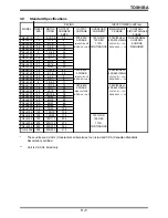
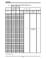
The customer supplied Molded Case Circuit Breaker (MCCB) or Magnetic Circuit
Protector (MCP) should be coordinated with the available short circuit current. The
units are rated for output short circuit faults of 5000A (1 - 50 HP), 10,000A (51 - 200 HP),
and 18,000A (201 - 400 HP) according to the UL 508 "Standard for Industrial Control
Equipment" Table 57B.4 or CSA Standard C22.2 No.14-M1987 "Industrial Control
Equipment" Table 24. The selection of breakers for this table is in accordance with
1987 NEC Article 430. The selection of these breakers takes into consideration motor
starting at the low end of the output voltage specifications but does not consider the
use of high efficiency motors.
*
For multiple motor applications, the magnetic only MCP should be replaced by a thermal
magnetic MCCB. The MCCB should be sized according to 1.25 X (largest motor Full
Load Amps) + (sum of all other motor Full Load Amps) to meet National Electric Code
(NEC) or Canadian Electrical Code (CEC) requirements.
**
Wire sizing is based upon NEC table 310-16 or CEC Table 2 using 75 deg C cable, an
ambient of 30 deg C, cable runs for less than 300 FT., and copper wiring for not more
than three conductors in raceway or cable or earth (directly buried). The customer
should consult the NEC or CEC wire Tables for his own particular application and wire
sizing.
**
For cable runs greater than 300 FT., consult the factory before installing.
***
Use two parallel conductors instead of a single conductor (this will allow for the proper
wire bending radius within the cabinet). Use separate conduits for routing parallel
conductors. This prevents the need for conductor derating (see note 3 this page).
Notes:
1.)
Auxiliary relays used to switch inverter signals should be capable of switching
low current signals (i.e. 5mA).
2.)
The inverter has internal overload protection, but the Local, National, or
Canadian Electrical Codes may require external motor overload protection.
3.)
When wiring with parallel conductors, the conductors should be kept together in
phase sets with U1, V1, W1 in one conduit and parallel conductors U2, V2, W2
in another conduit. The ground conductor should be in one of these conduits.
4.3
Grounding
The inverter should be grounded in accordance with Article 250 of the National Electrical
Code or Section 10 of the Canadian Electrical Code, Part I and the grounding conductor
should be sized in accordance with NEC Table 250-95 or CEC, Part I Table 16.
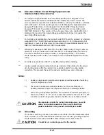
4 - 6
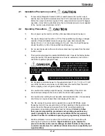
Conduit is not a suitable ground for the inverter.
CAUTION
Use separate conduits for routing incoming power, power to
motor, and control conductors. Use no more than three
power conductors and a ground conductor per conduit.
CAUTION
Содержание TOSVERT-130G2+
Страница 112: ...TOSHIBA 10 6 Schematics 10 17 ...

