background image

2-4

TLPB2 Service Manual    Rev. 2.0

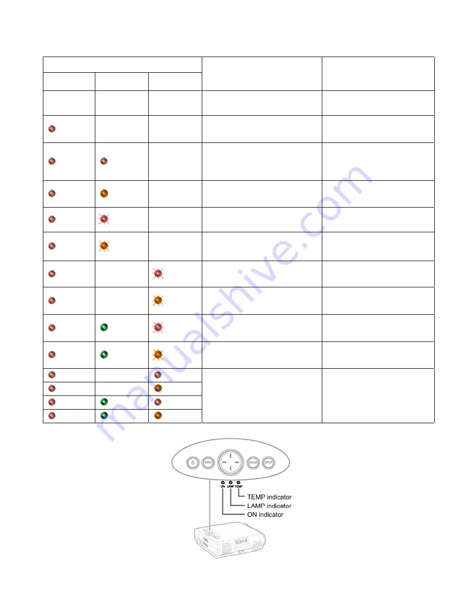
3.  LED DISPLAY  

(Problems Shown on Indicator Light)

Status of Indicator Light

ON

LAMP

TEMP

Description and Cause

Solution

-

-

-

Standby-power is not on.

> There’s a problem with the power unit or

system microcomputer.

Unplug the power cord and contact

your TOSHIBA dealer.

    Red

-

-

Power is not on.

> There’s a problem with the system

  microcomputer.

Unplug the power cord and contact

your TOSHIBA dealer.

    Red

    Red

-

The lamp went out during use or the lamp

will not switch on.

• The bulb has reached the end of it's life.

• Replace it with a new bulb.


Unplug the power cord and contact

your TOSHIBA dealer.

    Red

  Orange

-

The power went off during use, or the

power will not switch on.

> The lamp-exhaust fan is not working.

Unplug the power cord and contact

your TOSHIBA dealer.

    Red

  (Red)

-

The power will not switch on.

>The lamp cover is not close.

Close the lamp cover.

    Red

  (Orange)

-

The power went off during use, or the

power will not switch on.

>The lamp has overheated.

• Make sure that the openings for the

  intake and exhaust fans are not

 blocked.

• Clean the air filter.

    Red

-

  (Red)

The power went off during use, or the

power will not switch on.

> The Intake fan is not working.

Unplug the power cord and contact

your TOSHIBA dealer.

    Red

-

  (Orange)

The power went off during use, or the

power will not switch on.

> The Power-exhaust fan is not working.

Unplug the power cord and contact

your TOSHIBA dealer.

    Red

  Green

  (Red)

The power went off during use, or the

power will not switch on.

> The Lamp-exhaust fan is not working.

Unplug the power cord and contact

your TOSHIBA dealer.

    Red

  Green

  (Orange)

The power went off during use, or the

power will not switch on.

> The optical engine fan is not working.

Unplug the power cord and contact

your TOSHIBA dealer.

    Red

-

    Red

    Red

-

  Orange

    Red

  Green

    Red

    Red

  Green

  Orange

The power went off during use, or the

power will not switch on.

>The projector has overheated.

• Make sure that the openings for the

  intake and exhaust fans are not

 blocked.

• Turn off the power, let the projector

  sit for a while, and then turn it on

 again.

• Clean the air filter.

 (Red) : Red flashing,  (Orange):Orange flashing

Содержание TLP-B2E

Страница 1: ...3LCD DATA PROJECTOR SERVICE MANUAL TLPB2U TLPB2E TXPB2 TLPB2C FILE NO 330 200002 PRINTED IN JAPAN Jul 2000 F TLPB2 ...

Страница 2: ... time Measure the AC voltage across the combina tion of 1500ohm resistor and 0 15 µF capacitor Reverse the AC plug at the AC outlet and repeat AC voltage mea surements for each exposed metallic part Voltage mea sured must not exceed 5 25V rms This corresponds to 3 5 mA AC Any value exceeding this limit consti tutes a potential shock hazard and must be corrected immediately PRODUCT SAFETY NOTICE Ma...

Страница 3: ...3 9 LCD Panel 1 15 3 10 Multi PBS 1 19 3 11 Optical Engine FAN 1 20 3 12 Polarized Plate 1 21 3 13 Screws For Mechanical Parts 1 22 3 14 Screws For Optical Engine 1 23 4 OPTICAL ADJUSTMENT 1 24 5 ELECTRICAL ADJUSTMENT 1 28 SECTION 2 SERVICING DIAGRAMS 1 TROUBLE SHOOTING 2 1 2 CONNECTOR PIN ASSIGNMENT 2 3 3 LED DISPLAY 2 4 4 BLOCK DIAGRAM 2 5 5 CIRCUIT DIAGRAM 2 6 SECTION 3 PARTS LIST 1 SAFETY PREC...

Страница 4: ...e instruction manual may cause harmful interference to radio communications Operation of this equipment in a residential area is likely to cause harmful interference in which case the user will be required to correct the interference at his own expense WARNING Changes or modifications made to this equipment not expressly approved by Toshiba or parties authorized by Toshiba could void the user s au...

Страница 5: ... and to ensure reliable operation of the product and to protect it from overheating and these openings must not be blocked or covered The openings should never be blocked by placing the product on a bed sofa rug or other similar surface This product should not be placed in a built in installation such as a bookcase or rack unless proper ventilation is provided or the manufacturer s instructions ha...

Страница 6: ...ion to overturn IMPORTANT SAFETY INSTRUCTIONS 16 Damage Requiring Service Unplug this product from the wall outlet and refer servicing to qualified service personnel under the following conditions a When the power supply cord or plug is damaged b If liquid has been spilled or objects have fallen into the product c If the product has been exposed to rain or water d If the product does not operate n...

Страница 7: ...D ADJUSTMENT PROCEDURES 1 LOCATION OF MAIN PARTS 2 LOCATION OF PC BOARD P800 POWER SUPPLY P850 LAMP DRIVER E201 OPTICAL ENGINE LAMP HOUSING LCD BLOCK E101 MAIN PC BOARD E103 FAN PC BOARD E104 REM PC BOARD E102 AUDIO PC BOARD E201A PROJECTION LENS Z100 INTAKE FAN ...

Страница 8: ...ts are susceptible to static electricity and may easily be damaged so do not forget to take proper grounding treatment as required Many screws are used inside the unit To prevent missing dropping etc of the screws always use a magnetized screwdriver in servicing Several kinds of screws are used and some of them need special cautions That is take care of the tapping screws securing molded parts and...

Страница 9: ...de Remove four screws M2 6 x 6 Screw type M 1 2 Left Side Remove three screws M2 6 x 6 Screw type M 1 3 Bottom Remove one screw M2 6 x 6 Screw type M 1 4 Front Remove two screws M2 x 4 Screw type M 2 5 Remove front cover Note Unsnap the bottom first and then unsnap the top to remove ...

Страница 10: ...6 Push cabinet upward to remove back cover 7 Push down on the back cover to remove Note The back cover is fixed with the adhesion tape 8 Remove the top cover by lifting up on the left side of the cabinet and around the video connector ...

Страница 11: ... Service Manual Rev 2 0 3 3 Main PC Board Step Figure Explanation 1 Remove all cables and connectors 2 Remove five screws M2 6 x 6 Screw type M 1 3 Note There is no screw in the hole shown for the main PC board ...

Страница 12: ... x 6 Screw type M 1 2 Pull connector upward to remove 3 Remove three screws that secure the lamp housing and fan to the cabinet M2 6 x 6 Screw type M 3 Remove one screw that secures the lamp housing to the optical engine M2 6 x 6 Green marked Screw type M 1 4 Pull up the lamp housing upward 5 The lamp housing and exhaust fan are removed together ...

Страница 13: ...e exhaust fan module slides upward 7 Note The exhaust fan module is fixed in the rail 8 Note Separate the fan module from the lamp housing 9 Remove two screws M3 x 20 Screw type M 6 10 Fan holder and the exhaust fan are separated rail rail ...

Страница 14: ...Figure Explanation 1 Cut the cable tie with wire cutters 2 Loosen the cable clamp 3 Remove this screw M2 6 x 6 Screw type M 3 4 Remove this screw M2 6 x 6 Screw type M 3 5 Slide the power supply unit toward the front and lift up Note The power supply unit has two tabs at the bottom ...

Страница 15: ... EMC shield cover 7 The EMC shield cover is wrapped around the power supply unit 8 Release four PC mounts by using tweezers 9 Power supply unit and lamp driver are separated 10 Remove the connector which connects lamp driver with power supply unit ...

Страница 16: ...emove two screws M3 x 14 Screw type M 7 13 Power supply unit and exhaust fan are separated 14 Note Insert shield case in the clearance between the unit and aluminum case 15 Note Align the tab of the aluminum case in the hole of the shield case ...

Страница 17: ...PB2 Service Manual Rev 2 0 16 Note Insert the tabs from the power unit into the holder of the cabinet 17 Remove two screws 18 Remove aluminum plate 19 Be careful to lay an insulation seat Holder Tab Holder Tab ...

Страница 18: ...emove the screw that mounts the fan to the cabinet M2 6 x 6 Screw type M 3 2 Remove two screws M3 x 30 Screw type M 8 3 The fan PC board is between the intake fan and the dust filter holder 4 Install intake fan air guide adapter so air will not leak from the sub frame assembly ...

Страница 19: ...ard Step Figure Explanation 1 Remove four screws to remove the audio PC board M2 6 x 6 Screw type M 3 2 Note Place the two cable clamp on the connector side 3 Note The safety interlock switch is pushed when the lamp cover is replaced Switch Lamp Cover ...

Страница 20: ...ical engine M4 x 13 Screw type M 5 2 2 is near the lens 3 3 is near the power supply on the right side of the unit 4 4 is near the power supply on the left side of the unit 5 Place the unit where it is shown in the photograph and pull the optical engine up Note Be careful not to touch the projection lens 1 1 1 1 3 3 3 3 4 4 4 4 2 2 2 2 ...

Страница 21: ...p Figure Explanation 1 Remove three screws M3 x 6 Screw type E 1 Note Tear off adhesive tape when you remove the screw of A 2 Separate main frame and sub frame 3 Remove three screws M2 5 x 8 Screw type E 2 4 Separate prism block from main frame A A A A ...

Страница 22: ...rate the LCD panel and the mask and the bracket Note Leave the mask because it is used again yellow marked The LCD Panel and four screws are not used 7 Remove four screws M2 x 4 Screw type E 4 Note Leave the screws because they are used again 8 Note The removed bracket isn t used again ...

Страница 23: ... a new panel with four screws Note There are two kinds of types of the screw A Side Screw type E 5 B Side Screw type E 6 10 Four screws are to do temporary tightening 11 Tighten a new bracket with four screws M2 x 4 Screw type E 4 Note Four screws are tighten an old bracket A B ...

Страница 24: ...12 Install the LCD panel holder module made by step 9 13 Fix the LCD panel holder module on the bracket with two screws M2x2 Screw type E 7 14 Fix a prism block on the main frame Note Panel holder service kit E205S 23430870 E 5 E 6 E 7 ...

Страница 25: ...MULTI PBS Polarizing Beam Splitter Step Figure Explanation 1 Remove four screws M2 5 x 6 Screw type E 8 2 Lift the Multi PBS with tweezers a little 3 Remove the Multi PBS 4 Note Be careful in the direction which it is installed in Lamp Prism ...

Страница 26: ...1 20 TLPB2 Service Manual Rev 2 0 5 Insert the Multi PBS 6 Put a metal fitting in the gap 3 11 Optical Engine Cooling FAN 1 Remove four screws M2 5 x 16 Screw type E 9 ...

Страница 27: ...e Step Figure Explanation 1 Lift a stopper by using the tweezers 2 Remove a stopper 3 Remove a polarized plate 4 Note Be careful in the direction which it is installed in Be careful of the color color have to match with LCD panel Panel Side Color Marking ...

Страница 28: ...5 Lamp house 1 Lamp cable connector 1 Top cover 8 Lamp cover 2 M 2 2 x 4 Front cover 2 M 3 2 6 x 6 Audio PCB 4 Rem PCB 1 Intake FAN module 1 Lamp house 1 Exhaust FAN module 2 M 4 3 x 8 Thermo sensor 1 Wire holder 1 M 5 3 x 12 Optical Engine 4 M 6 3 x 20 Exhaust FAN 2 M 7 3 x 14 Power FAN 2 M 8 3 x 30 Intake FAN 2 ...

Страница 29: ...and Sub Frame 3 E 3 M2 5 x 6 LCD PANEL 4 Not used after remove old panel E 4 M2 x 4 Bracket 4 E 5 M2 5 x 6 LCD Panel connector side 2 Contained in Panel Service Kits E 6 M2 5 x 6 LCD Panel 2 Contained in Panel Service Kits E 7 M2 x 2 LCD Panel Bracket 2 Contained in Panel Service Kits E 8 M2 5 x 6 Multi PBS Cover 4 E 9 M2 5 x 16 PBS Cooling FAN 2 ...

Страница 30: ...23588620 10p extension cable 23588620 1 Setting Put PJ on the horizontal place and project it on the vertical screen 2 Disconnect the following connectors Disconnect PJ851 PJ901 PJ951 PJ990 Disconnect PJ1 Remove Thermo Switch P100 form lamp housing 3 Connect extension cable Connect PJ851 and R Panel with extension cable Connect PJ901 and G Panel with extension cable Connect PJ951 and B Panel with ...

Страница 31: ...ating software SINGO98 exe Click cross hatch button Click R and B button to display G Cross Hatch 5 Focus Adjustment When a screw A is loosened the panel moves to front and back and focus can be adjusted When the screws B are loosened the panel moves to left right up and down and convergence can be adjusted A B B B B ...

Страница 32: ... exchange Step Figure Explanation 1 TEST PATTERN Green Cross Hatch Adjust focus by projection Lens 2 TEST PATTERN Blue Cross Hatch Move a panel in front and back and adjust a focus Tighten two screws little by little 3 4 Tighten two screws when you reached best focus point ...

Страница 33: ...1 27 TLPB2 Service Manual Rev 2 0 5 TEST PATTERN Blue and Green Cross Hatch Move a panel in left right up and down and adjust a convergence 6 7 Tighten four screws ...

Страница 34: ... is started a screen like the following image Fig 1 4 2 appears Fig 1 4 2 Shading Compensation Î When a Main PC board will be replaced Before replacing download the current data from PJ After replacing upload the current data to new PCB Electrical Adjustment Î When the LCD panels or the Main PC board are replaced Error List ÎWhen the error code which occurred by now is examined Software Upgrade ÎW...

Страница 35: ...1 29 TLPB2 Service Manual Rev 2 0 3 TEST POINTS TP R TP G TP B TP R TP G TP B ...

Страница 36: ...ep Figure Explanation 1 Press the Shading Compensation button 2 Press Download button The current shading data will be read form projector and be saved this data to Personal Computer 3 After replacing the Main PC Board press Upload button The shading data in the old PCB will be written to the projector ...

Страница 37: ...rd and LCD Panels then select the Main PCB and LCD button Î 5 3 2 5 3 1 When a panel was replaced 5 3 1 1 Flicker Adjustment Step Figure Explanation 1 Input Signal RGB flicker pattern 1 Select a red single color screen when adjusting R Click the WM6 button and adjust the flicker level to minimum in both and directions taking note of the data values Then set data to the mid point between the two pr...

Страница 38: ...elected data to the projector 3 After writing shading data when a progress bar is disappeared press Next button 2 1 Press Next button 5 3 1 3 Adjustment of Color Temperature 1 Input Signal 50 RGB white 1 Click W03 and or W05 buttons and adjust screen to be natural gray 2 Click Next button 2 Input Signal 50 Video white 1 Click W03 and or W05 buttons and adjust screen to be natural gray 2 Click Next...

Страница 39: ...ion 1 1 Click the Setup of Shipping button and set the default Note If you click the Setup of Shipping then Total working time Lamp timer and User memory are initialized 2 Click the Version Check button and check the Software version and Total working time ...

Страница 40: ...ilable 2 1 Press Next button Note When the measurement of three statuses are completed Next button will be available These three measured data are used for the compensation of the gravity sensor 5 3 2 2 Adjustment of Input Signal Level Note TEST POINT TP R TP G TP B refer to page 1 29 1 Input Signal RGB 15 step signal 1 Monitor the waveform at the respective test point TP R when you adjust the R l...

Страница 41: ...um in both and directions taking note of the data values Then set data to the mid point between the two previously noted values 2 Adjust other colors to be the same using WM5 for green and WM4 for blue 3 Click the Upside Down button to change projection mode 4 Adjust this mode in the same way 5 Click Next buttons Recommendation value 40 50 4 1 Monitor the waveform at test point TP R 2 Click the W0...

Страница 42: ... mode Please ensure that you have a video pattern generator connected 1 Monitor the waveform at test point TP R 2 Click the W03 button and adjust to the specified level 3 Click Next button 8 1 Monitor the waveform at test point TP G 2 Click the W04 button and adjust to the specified level 3 Click Next button 9 1 Monitor the waveform at test point TP B 2 Click the W05 button and adjust to the speci...

Страница 43: ...lected data to the projector 3 After writing shading data when a progress bar is disappeared press Next button 5 3 2 4 Compensation of Keystone Data after heat run 1 1 Set the projector horizontally and click the KC3 button Note The deviation of the inclination sensor due to rise in temperature is corrected by measuring after warming up for approximately one hour 2 1 Press Next button ...

Страница 44: ... Input Signal RGB 50 White 1 Click W03 and or W05 buttons and adjust screen until it becomes a natural gray 2 Click Next button 5 3 2 6 Final Inspection 1 1 Click the Setup of Shipping button and set the default Note If you click the Setup of Shipping then Total working Time Lamp timer and User memory are initialized 2 Click the Version Check button and check the Software version and Total working...

Страница 45: ...g pattern See 2 4 Lamp is not on Lamp Fractured or not Fractured ÎChange new lamp Not Fractured ÎCheck Lamp cover or PJ3 No Signal on screen display Indicated or not Indicated ÎRGB Video terminal is NG or Main PCB is NG Not Indicated Î Check next step No image Test Point TP R TP G TP B Signal shape Correct Î LCD panel is NG or PJ851 PJ901 PJ951 is NG Incorrect Î Main PCB is NG ATTENTION LED displa...

Страница 46: ... SERVICE SOFTWARE 1 Start service software TLPB2S EXE 2 Reading of the error list 3 The point of view of the indication Click Error List button Click Read button The number of times which occurred in the past The error which occurred recently ...

Страница 47: ...ower Supply 1 FAN Power 13V 2 FAN Drive 1V to 13V Pulse 3 N C 4 N C PJ503 MAIN Exhaust FAN Lamp 1 FAN Power 13V 2 FAN Drive 1V to 13V Pulse PJ504 MAIN Cooling FAN Optical Engine 1 FAN Power 13V 2 GND FAN 0V 3 FAN Error 0V to 5V OK Pulse NG Stable PJ851 PJ901 PJ951 MAIN LCD PANEL 1 VSSY 0V 2 DIRY 0V 15 5V 3 DY 0V to 15 5V Pulse 4 LCCOM 6V 5 NRS 2V to 8V 6 VID12 2V to 12V Video 7 VID11 2V to 12V Vid...

Страница 48: ...e lamp has overheated Make sure that the openings for the intake and exhaust fans are not blocked Clean the air filter Red Red The power went off during use or the power will not switch on The Intake fan is not working Unplug the power cord and contact your TOSHIBA dealer Red Orange The power went off during use or the power will not switch on The Power exhaust fan is not working Unplug the power ...

Страница 49: ... U P P L Y U N I T P J 5 0 2 P J 5 0 4 P J 5 0 3 P J 4 0 0 P J 1 P J 9 9 0 P J 4 0 1 P J 2 P J 3 P J 6 0 2 P J 6 0 4 P J 4 5 0 P J 4 5 2 P J 4 5 1 P J 5 5 1 P J 8 5 1 P J 9 5 1 P J 9 0 1 L C D B L C D G A C I N 2 5 T L P B 2 S e r v i c e M a n u a l R e v 1 0 4 B L O C K D I A G R A M 4 BLOCK DIAGRAM ...

Страница 50: ...2 6 TLPB2 Service Manual Rev 2 0 ...

Страница 51: ... not have the same safety characteristics as specified in the parts list may create shock fire or other hazards NOTICE The part number must be used when ordering parts in order to assist in processing be sure to include the model number and description Parts marked are of chip type and mounted on original PC boards However when they are placed for servicing works use discrete parts listed on the p...

Страница 52: ...3 2 TLPB2 Service Manual Rev 2 0 3 2 Packing Assembly Y260 23448590 A410 23064229 A403 23946039 Y404 23945095 A400 23064228 Y401 23564310 B2U 23564311 B2E Note Refer to page 3 8 for parts description ...

Страница 53: ...8733 PC Audio Cable Y207 for B2E 23563935 Y293 23368571 Video Cable Y210 Y211 Y212 Y213 Y214 Y215 23589124 23589125 23589126 23589127 23589128 23589129 Y102 23368750 RGB Cable Y202 23956184 Sticker Cable Y110 23368679 Mac Adapter Y203 23956185 Sticker Function for B2U 23372144 23372148 Y119 23589121 Accessories List Y205 for B2E 23372145 23372147 Y260 23448590 Soft Case Y206 for B2E 23372149 Y250 ...

Страница 54: ...83 Fan Motor P200 23351159 Speaker B100 23411361 Bottom cover Z100 23125881 Fan motor A242 23466910 Air Filter Mesh A241 23466909 Air Filter Sponge A240 23540046 Cover Filter A220 23540056 Cover Assy Front A270 23540057 Cover Lens A260 23540047 Cover Assy Lamp B180 B180 B200 B153 P100 23344455 Switch NOT SPARE PARTS ...

Страница 55: ...5 PC Board and Power Unit Assembly E103 23771029 P C B Fan E101 23771027 P C B Main E104 23771030 P C B Remote E102 23771028 P C B Audio P800 23122389 Main Power Unit Z102 23125884 Fan Motor P850 23122388 Lamp Power B122 NOT SPARE PARTS ...

Страница 56: ...ngine Assembly E201G 23430766 PBS E201F 23430763 Polarizar Blue E201E 23430764 Polarizar Green E201D 23430765 Polarizar Red E201A 23430760 Lens E201H 23588619 Fan Motor MAIN FRAME E201B 23430761 SUB FRAME E201C 23430762 OPTICAL ENGINE E201 23430759 ...

Страница 57: ... 3 7 Labels A300 23564297 Tag Sheet Rear A304 23564424 Caution Label A301 23564308 B2E Rating Label A312 23564301 Caution Label Lamp A311 23564300 Caution Label Hot A310 23564299 Caution Label Lens A313 23564302 Caution Label AC cord ...

Страница 58: ...ITS JIG E205S 23430870 Panel Holder Service Kit M005S 23588620 10p Extension Cable M100S 23588552 Service Kit include Extension Cable LOCATION NUMBER PARTS NUMBER DESCRIPTION ACCESSORY PARTS Y102 23368750 RGB Cable Y105 23368733 Audio Cable Stereo Mini Y106 23368676A Serial Cable Y110 23368679 Mac Adapter Y119 23589121 Sheet Accessory Y200 23563936 Owner s Manual CD ROM Y201 23563933 Owner s Manua...

Страница 59: ......

Отзывы: