Page 174
16. OTP operation
16.1 Operating mode
TMP86PM29BUG
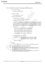
16.1.2.2 Program Writing using a General-purpose PROM Programmer
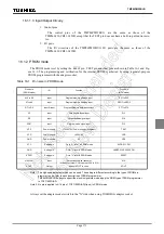
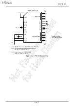
1. Recommended OTP adaptor
BM11662 for TMP86PM29BUG
2. Setting of OTP adaptor
Set the switch (SW1) to "N" side.
3. Setting of PROM programmer
a. Set PROM type to TC571000D/AD.
Vpp: 12.75 V (high-speed program writing mode)
b. Data transmission ( or Copy) (Note 1)
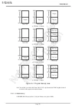
The PROM of TMP86PM29BUG is located on different address; it depends on operating
mode: MCU mode and PROM mode. When you write the data of ROM for mask ROM prod-
ucts, the data shuold be transferred (or copied ) from the address for MCU mode to that for
PROM mode before writing operation is executed. For the applicable program areas of MCU
mode and PROM mode are different, refer to TMP86PM29BUG" Figure 16-1 Program
Memory Area ".
Example: In the block transfer (copy) mode, executed as below.
32KB ROM capacity: 08000~0FFFFH
→
00000~07FFFH
16KB ROM capacity: 0C000~0FFFFH
→
04000~07FFFH
8KB ROM capacity : 0E000~0FFFFH
→
06000~07FFFH
4KB ROM capacity : 0F000~0FFFFH
→
07000~07FFFH
c. Setting of the program address (Note 1)
Start address: 0000H (When 16 KB ROM capacity, start address is 4000H.
When 8 KB ROM capacity, start address is 6000H.
When 4KB ROM capacity, start address is 7000H.)
End address: 7FFFH
4. Writting
Write and verify according to the above procedure "Setting of PROM programmer".
Note 1: For the setting method, refer to each description of PROM programmer.
Make sure to set the data of address area that is not in use to FFH.
Note 2: When setting MCU to the adaptor or when setting the adaptor to the PROM programmer, set the first
pin of the adaptor and that of PROM programmer socket matched. If the first pin is conversely set,
MCU or adaptor or programmer would be damaged.
Note 3: The TMP86PM29BUG does not support the electric signature mode.
If PROM programmer uses the signature, the device would be damaged because of applying voltage
of 12
±
0.5V to pin 9(A9) of the address. Don’t use the signature.
Содержание TLCS-870/C Series
Страница 1: ...8 Bit Microcontroller TLCS 870 C Series TMP86PM29BUG ...
Страница 6: ...TMP86PM29BUG ...
Страница 7: ...Revision History Date Revision 2007 10 11 1 First Release 2008 8 29 2 Contents Revised ...
Страница 9: ......
Страница 15: ...vi ...
Страница 19: ...Page 4 1 3 Block Diagram TMP86PM29BUG 1 3 Block Diagram Figure 1 2 Block Diagram ...
Страница 23: ...Page 8 1 4 Pin Names and Functions TMP86PM29BUG ...
Страница 48: ...Page 33 TMP86PM29BUG ...
Страница 49: ...Page 34 2 Operational Description 2 3 Reset Circuit TMP86PM29BUG ...
Страница 61: ...Page 46 3 Interrupt Control Circuit 3 8 External Interrupts TMP86PM29BUG ...
Страница 81: ...Page 66 6 Watchdog Timer WDT 6 3 Address Trap TMP86PM29BUG ...
Страница 135: ...Page 120 10 8 Bit TimerCounter TC5 TC6 10 1 Configuration TMP86PM29BUG ...
Страница 145: ...Page 130 11 Asynchronous Serial interface UART 11 9 Status Flag TMP86PM29BUG ...
Страница 165: ...Page 150 13 10 bit AD Converter ADC 13 6 Precautions about AD Converter TMP86PM29BUG ...
Страница 183: ...Page 168 15 LCD Driver 15 4 Control Method of LCD Driver TMP86PM29BUG ...
Страница 201: ...Page 186 18 Electrical Characteristics 18 9 Handling Precaution TMP86PM29BUG ...
Страница 203: ...Page 188 19 Package Dimensions TMP86PM29BUG ...
Страница 205: ......

